
Adjustable annuloplasty ring activation system

a technology of annuloplasty and activation system, which is applied in the field of annuloplasty rings, can solve the problems of ineffective closure of valve leaflets, insufficient valve leaflets, and inability to regulate the flow of blood through the valve,

Inactive Publication Date: 2012-08-30
MICARDIA CORP
View PDF6 Cites 31 Cited by
  • Summary
  • Abstract
  • Description
  • Claims
  • Application Information

AI Technical Summary

Benefits of technology

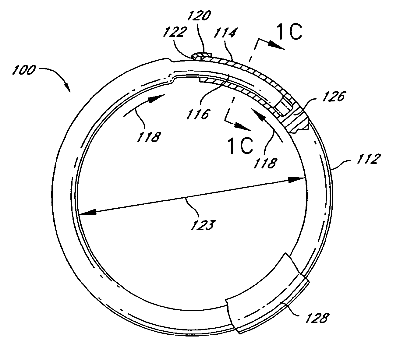
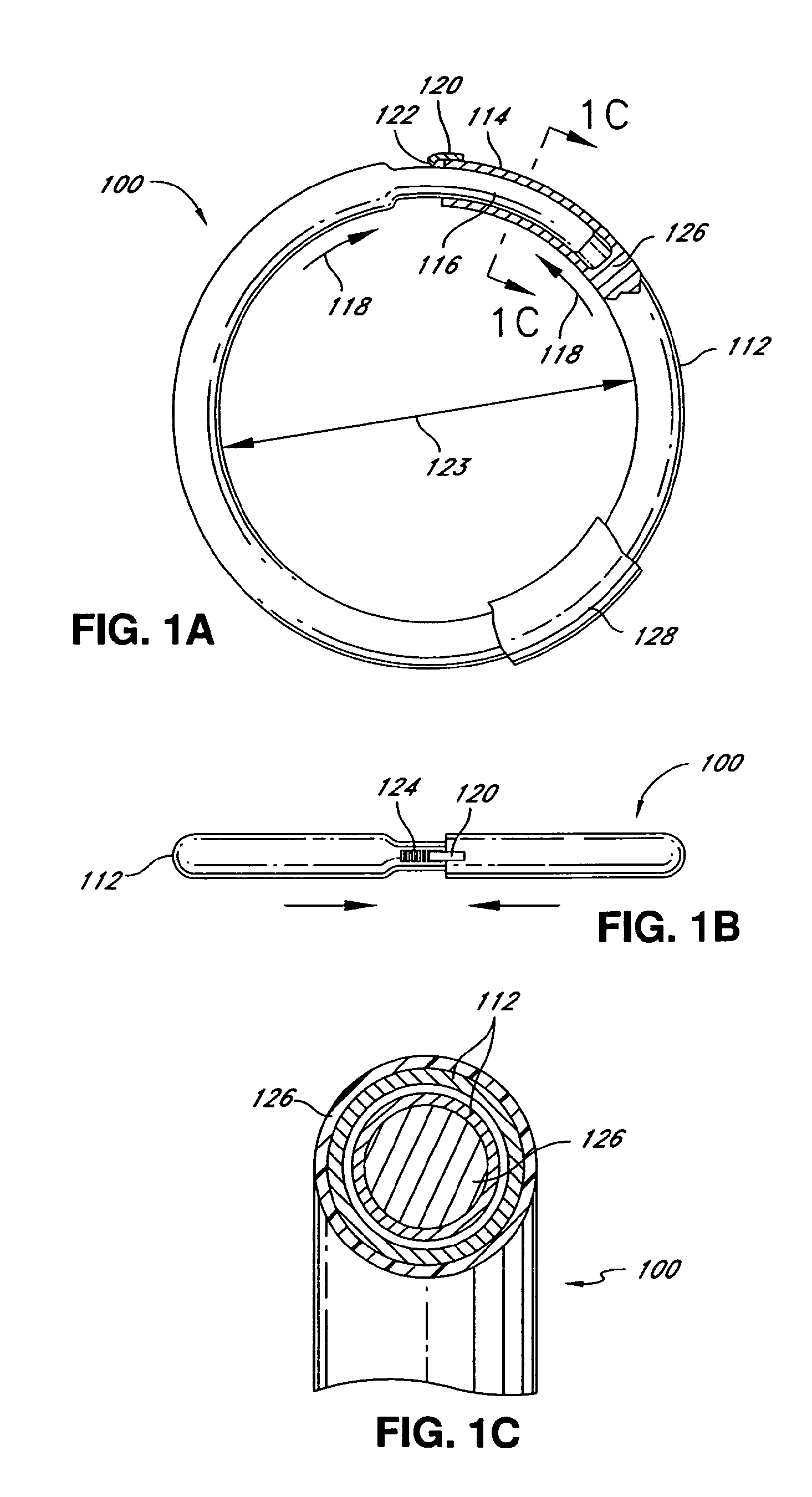
"The patent describes an adjustable annuloplasty device for reinforcing a heart valve annulus or other body structure using a shape memory material and a hysteretic material that can be activated by a magnetic field. The device can be adjusted in size to change the dimension of the valve annulus or other body structure. The device can be implanted using a minimally invasive or non-invasive method and can be adjusted in response to a magnetic field or other activation energy. The technical effect of the patent is to provide a device and method for adjusting the shape of a heart valve annulus or other body structure that can be done in a minimally invasive or non-invasive way."

Problems solved by technology

If the valves of the heart do not function properly, due either to disease or congenital defects, the circulation of the blood may be compromised.
Diseased heart valves may be stenotic, wherein the valve does not open sufficiently to allow adequate forward flow of blood through the valve, and / or incompetent, wherein the valve does not close completely.
Incompetent heart valves cause regurgitation or excessive backward flow of blood through the valve when the valve is closed.
When a heart valve annulus dilates, the valve leaflet geometry deforms and causes ineffective closure of the valve leaflets.
The ineffective closure of the valve can cause regurgitation of the blood, accumulation of blood in the heart, and other problems.
Although the implantation of an annuloplasty ring can be effective, the heart of a patient may change geometry over time after implantation.
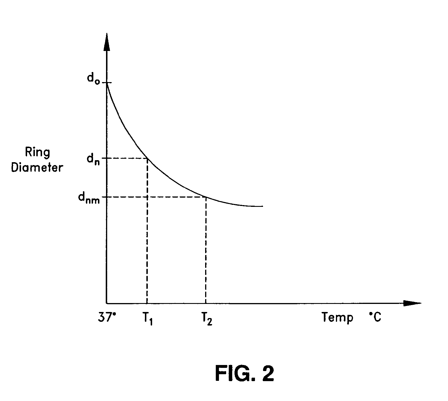
Whether the size of the heart grows or reduces after implantation of an annuloplasty ring, the ring may no longer be the appropriate size for the changed size of the valve annulus.

Method used


Image

  • Adjustable annuloplasty ring activation system
  • Adjustable annuloplasty ring activation system
  • Adjustable annuloplasty ring activation system

Examples


Embodiment Construction

[0079]The invention may be embodied in other specific forms without departing from its spirit or essential characteristics. The described embodiments are to be considered in all respects only as illustrative and not restrictive. The scope of the invention is therefore indicated by the appended claims rather than the foregoing description. All changes that come within the meaning and range of equivalency of the claims are to be embraced within their scope.

[0080]The present invention involves systems and methods for reinforcing dysfunctional heart valves and other body structures with adjustable rings. In certain embodiments, an adjustable annuloplasty ring is implanted into the body of a patient such as a human or other animal. The adjustable annuloplasty ring is implanted through an incision or body opening either thoracically (e.g., open-heart surgery) or percutaneously (e.g., via a femoral artery or vein, or other arteries or veins) as is known to someone skilled in the art. The a...


PUM


Abstract

An adjustable annuloplasty device is described. The device includes a body member comprising a shape memory material, the body member configured to be placed at or near a base of a valve of a heart. The device further includes a hysteretic material configured to undergo magnetic hysteresis in response to a first activation energy, the hysteretic material being in thermal communication with the shape memory material. The body member may have a first size of a body member dimension in a first configuration and a second size of the body member dimension in a second configuration. When the body member is in position in the heart, a change from the first configuration to the second configuration changes a size of a dimension of the annulus of the valve.

Description

RELATED APPLICATIONS[0001]This application is a continuation of U.S. patent application Ser. No. 11 / 638,501 filed on Dec. 14, 2006 which claims the benefit under 35 U.S.C. §119(e) of U.S. Provisional Patent Application No. 60 / 750,974, filed Dec. 16, 2005; this application is also a continuation-in-part of U.S. patent application Ser. No. 11 / 124,364, filed May 6, 2005, which claimed priority to both U.S. Provisional Application No. 60 / 584,432, filed Jun. 29, 2004, and to U.S. patent application Ser. No. 11 / 181,686, filed Jul. 14, 2005, which claimed priority to U.S. Provisional Application No. 60 / 588,253, filed Jul. 15, 2004; this application is also a continuation-in-part of U.S. patent application Ser. No. 11 / 124,409, filed May 6, 2005, which claimed priority to both U.S. patent application Ser. No. 11 / 181,686, filed Jul. 14, 2005, which claimed priority to U.S. Provisional Application No. 60 / 588,253, filed Jul. 15, 2004, and to U.S. Provisional Application No. 60 / 584,432, filed Ju...

Claims


Application Information

Patent Timeline
Patent Type & Authority Applications(United States)
IPC IPC(8): A61F2/24
CPCA61F2/2445A61F2/2448A61F2250/0004A61F2210/009A61F2250/0001A61F2210/0038
Inventor MOADDEB, SHAWNSHAOLIAN, SAMUELDABNEY, JAMES HUNTINGTONSAWICZ, CONRADLENKER, JAY A.
Owner MICARDIA CORP
Learn More