
Mobile Communication Device and Antenna Structure Therein

a mobile communication and antenna technology, applied in the direction of antennas, antenna details, elongated active element feed, etc., can solve the problem that the band cannot cover the eight-band, and achieve the effect of effectively excite the shorted radiation portion and easy integration with neighboring components

Active Publication Date: 2012-08-30
ACER INC
View PDF3 Cites 16 Cited by
  • Summary
  • Abstract
  • Description
  • Claims
  • Application Information

AI Technical Summary

Benefits of technology

[0007]In order to solve the abovementioned problems, it is one of the objectives of the present invention to provide a mobile communication device and a related antenna structure covering the eight-band LTE / WWAN operation and having a shielding metal wall to effectively perform the integration of its built-in antenna with electronic elements of the mobile communication device.
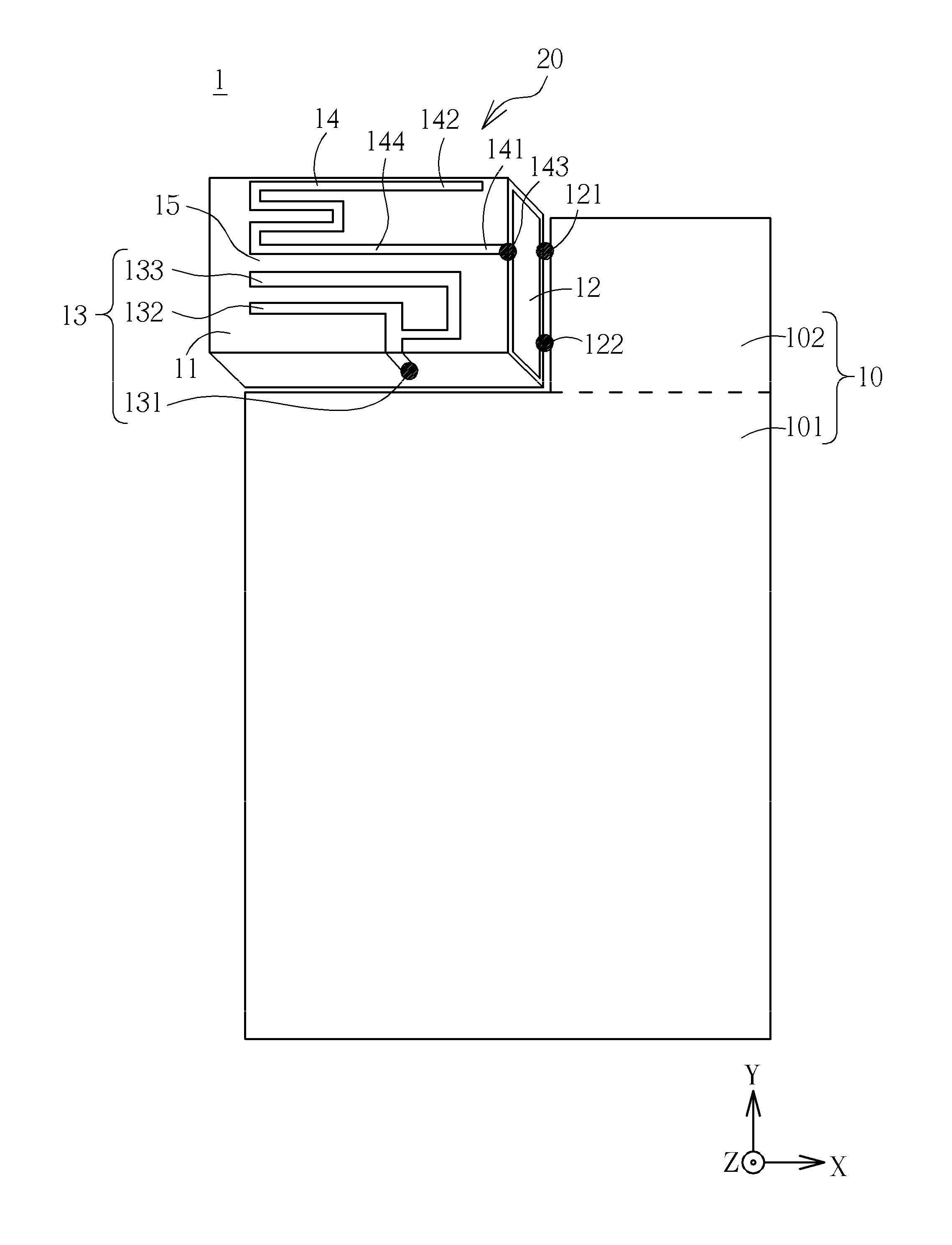
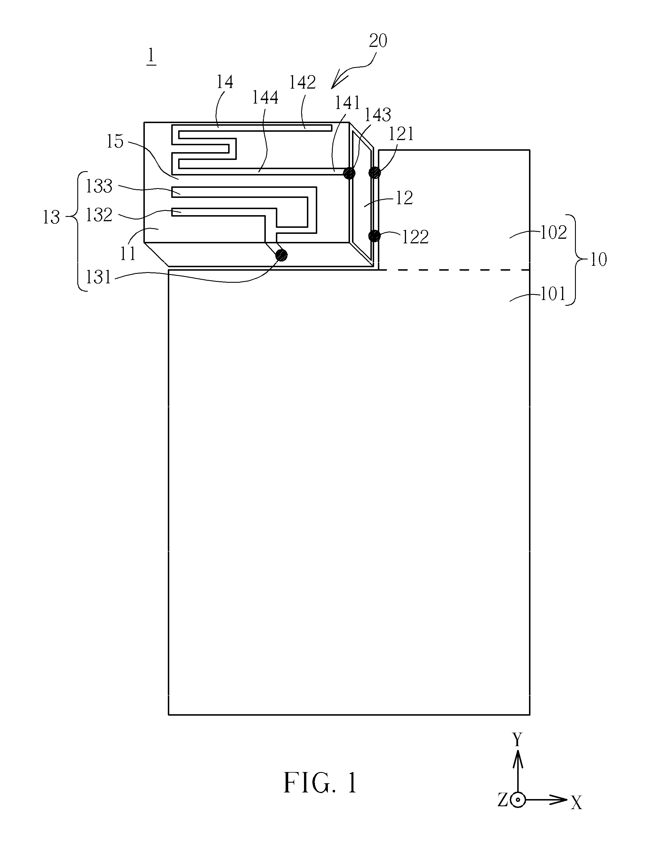
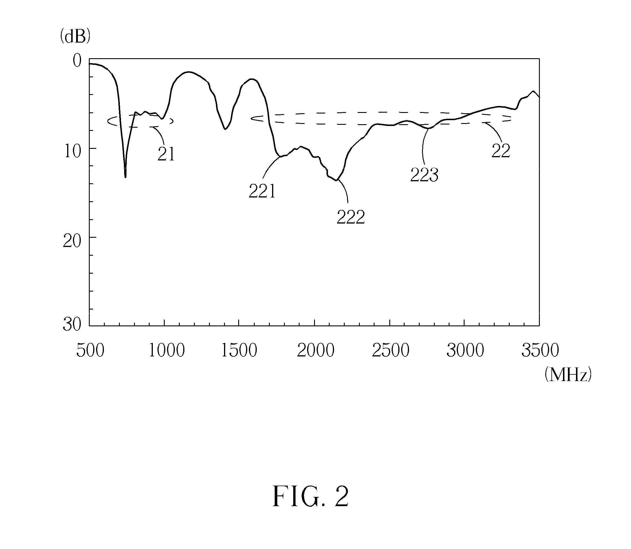
[0010]The present invention includes the following advantages. The multiband antenna of the mobile communication device uses its antenna ground plane as a shielding metal wall. In addition, the sections with a strong current (or the sections with a weak electric field) of the radiation portion and the shorted radiation portion are disposed adjacent to the antenna ground plane, such that the multiband operation of the antenna won't be affected by the antenna ground plane, and the internal antenna can be tightly integrated with other electronic elements on the system circuit board of the device. The major design mechanism of the multiband antenna is to use two radiation portions with two different lengths and extended toward the same direction to generate two resonant modes with different center frequencies at the higher frequencies, such that these two resonant modes can cover most bandwidth of the second (higher frequency) operating band. Moreover, the extended direction of the radiation portion keeps the open end of the radiation portion away from the antenna ground plane. By using a coupling gap between the designated section of the shorted radiation portion close to the shorting end and the radiation portion, the shorted radiation portion can be excited. Be noted that: the coupling gap is less than 3 mm, and the length of the shorted radiation portion is at least twice the shortest resonant path of the radiation portion, such that the energy of the radiation portion can be coupled to the shorted radiation portion in order to effectively excite the shorted radiation portion. As a result, the first (lower-frequency) operating band covering the three-band LTE700 / GSM850 / 900 operation (from about 704 MHz to 960 MHz) can be formed, and another higher-order resonant mode can be excited at the higher frequencies. Then, the higher-order resonant mode can be combined with the resonant mode excited by the radiation portion in order to form a wideband second (higher-frequency) operating band at least covering the five-band GSM1800 / 1900 / UMTS / LTE2300 / 2500 operation (from about 1710 MHz to 2690 MHz) to satisfy the eight-band LTE / WWAN operation, which can satisfy requirements of covering operating bands of all mobile communication systems at present. Furthermore, since the multiband antenna of the mobile communication device has a small size of 3×15×35 mm3 and a shielding metal wall, and can be easily integrated with neighboring components, it can satisfy requirements of practical applications.

Problems solved by technology

Such multiband meandered loop antenna has an operating band covering the five-band WWAN operation, however, its operating band cannot cover the eight-band LTE / WWAN operation.

Method used


Image

  • Mobile Communication Device and Antenna Structure Therein
  • Mobile Communication Device and Antenna Structure Therein
  • Mobile Communication Device and Antenna Structure Therein

Examples


Embodiment Construction

[0016]The following description is of the best-contemplated mode of carrying out the present invention. A detailed description is given in the following embodiments with reference to the accompanying drawings.

[0017]Certain terms are used throughout the description and following claims to refer to particular components. As one skilled in the art will appreciate, manufacturers may refer to a component by different names. This document does not intend to distinguish between components that differ in name but not function. In the following description and in the claims, the terms “include” and “comprise” are used in an open-ended fashion, and thus should be interpreted to mean “include, but not limited to . . . ”. Also, the term “couple” is intended to mean either an indirect or direct electrical connection. Accordingly, if one device is coupled to another device, that connection may be through a direct electrical connection, or through an indirect electrical connection via other device...


PUM


Abstract

A mobile communication device having an antenna structure includes a grounding element and an antenna element. The antenna element includes an antenna ground plane, a radiation portion, and a shorted radiation portion, wherein the antenna ground plane is grounded to the grounding element. The radiation portion includes a signal feeding point, a first radiation section, and a second radiation section. First and second radiation sections are connected to the signal feeding point, and are extended toward the same direction. First end of the shorted radiation portion is electrically connected to the antenna ground plane, and second end is left open. There is a coupling gap between a designated section of the radiation portion close to the first end and the shorted radiation portion. Through the coupling gap, the shorted radiation portion is capacitively excited by the radiation portion and generates at least one resonant mode to increase antenna's operating bandwidth.

Description

BACKGROUND OF THE INVENTION[0001]1. Field of the Invention[0002]The present invention relates to a mobile communication device and an antenna structure therein, and more particularly, to a mobile communication device with a built-in antenna having a shielding metal wall and multi-frequency operating bands.[0003]2. Description of the Prior Art[0004]With the rapid progress of wireless technology, the long term evolution (LTE) mobile technology has been promoted. Antennas of mobile communication devices are required to have lower operating frequencies and wider bandwidths, that is, their operating bands must cover from about 704 MHz to 960 MHz and from about 1710 MHz to 2690 MHz so as to satisfy the three-band LTE700 / 2300 / 2500 operation and the five-band WWAN operation. Mobile communication devices are required to be light and small, such that small size and multi-band operations become essential design considerations. Furthermore, under multi-functional demands, the integration of an ...

Claims


Application Information

Patent Timeline
Patent Type & Authority Applications(United States)
IPC IPC(8): H01Q5/00H01Q9/04H01Q5/371H01Q5/392
CPCH01Q1/243H01Q1/38H01Q5/392H01Q5/371H01Q9/42
Inventor WONG, KIN-LUCHEN, SHU-CHUAN
Owner ACER INC
Learn More