
Tilt Detecting Device And Laser Surveying Instrument

a detection device and detecting technology, applied in the field of tilt detection devices and laser surveying instruments, can solve the problems of low accuracy, complicated encoder mechanism, and low resolution of gravity sensors, and achieve the effect of high accuracy and low accuracy

Active Publication Date: 2012-08-30
KK TOPCON
View PDF7 Cites 25 Cited by
  • Summary
  • Abstract
  • Description
  • Claims
  • Application Information

AI Technical Summary

Benefits of technology

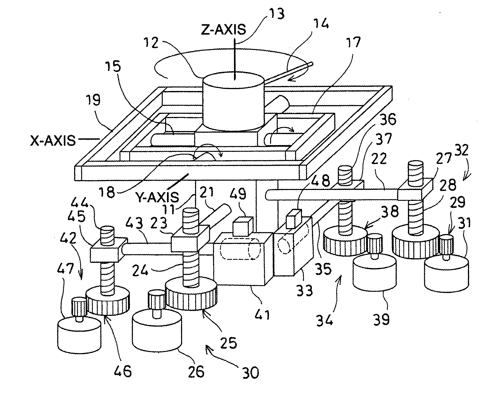
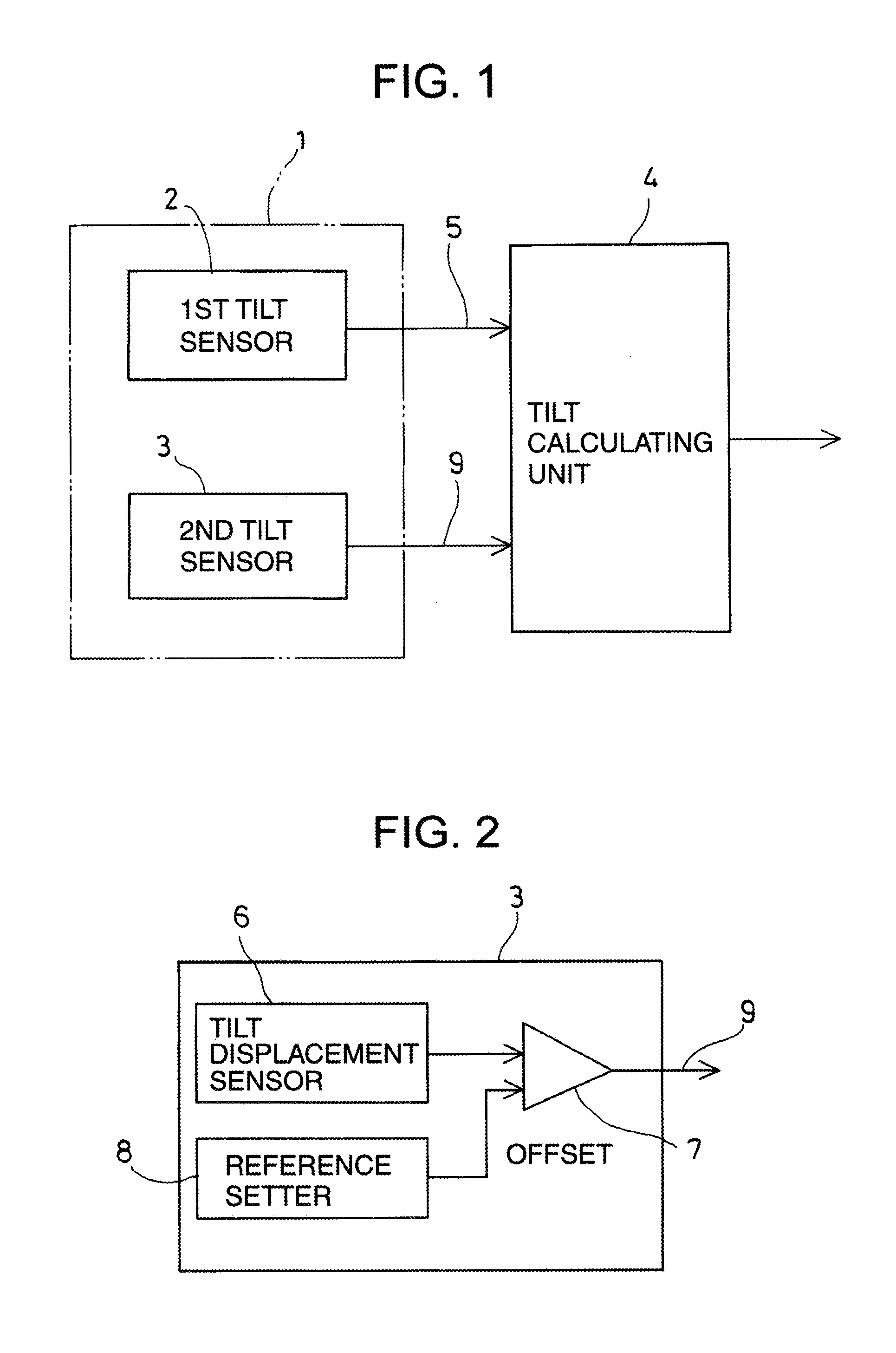
The present invention provides a tilt detecting device with high accuracy for detecting tilting with respect to direction of gravity. The device includes a first tilt sensor and a second tilt sensor, with the second tilt sensor having lower accuracy but wider detection range. The second tilt sensor can detect tilting based on a reference position and the detection direction from the first tilt sensor. The device can be used in a laser surveying instrument, which includes a laser beam projector and a drive unit for tilting the laser beam projector. The tilt detecting device is fixed relative to the laser beam projector, and the laser beam projector is tilted based on the result of detection by the second tilt sensor from a condition where the first tilt sensor detects horizontality. The technical effect of the invention is to provide a reliable and accurate means for detecting tilting in a laser surveying instrument.

Problems solved by technology

However, in the tilt detecting device disclosed in the Patent Document 1, there are problems that the mechanism of the encoder is complicated and that higher cost is required.
In the tilt detecting device as disclosed in the Patent Document 2, the horizontality can be detected with high accuracy, but the tilt angle is detected by using the gravity sensor, and the gravity sensor has lower resolution (lower detection accuracy).
For this reason, the tilt detecting device according to the Patent Document 2 has simple structure, but there is a problem in that the detection accuracy to detect the tilt angle is low.

Method used


Image

  • Tilt Detecting Device And Laser Surveying Instrument
  • Tilt Detecting Device And Laser Surveying Instrument
  • Tilt Detecting Device And Laser Surveying Instrument

Examples


first embodiment

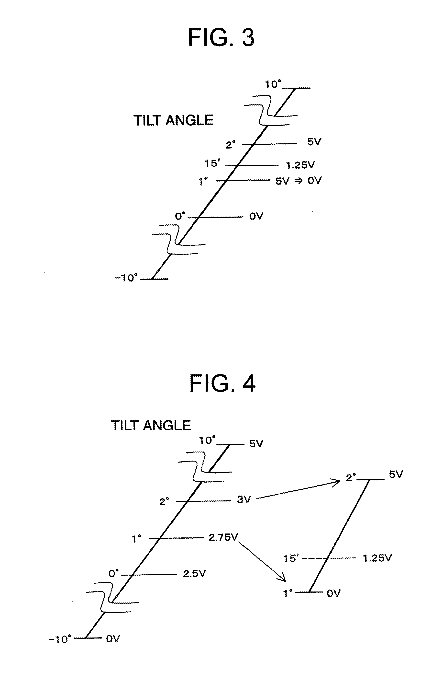
[0060]Next, referring FIG. 3, description will be given on operation of tilt detection by the tilt detecting device 1 according to the

[0061]In the first embodiment, a reference voltage (offset voltage) to be applied to the amplifier 7 is set so that output voltage from the amplifier 7 at every predetermined angle is to be 0 V every time an angle detected by the tilt displacement sensor 6 is beyond the predetermined angle.

[0062]For instance, as shown in FIG. 3, it is assumed that the tilt displacement sensor 6 detects the tilting in the range of −10° to +10°, and that output voltage of the amplifier 7 is 5 V at maximum (i.e. dynamic range is 5 V at maximum). Each time the second tilt sensor 3 detects 1°, the reference setter 8 sets the reference voltage to be applied to the amplifier 7 so that the output voltage from the amplifier 7 will be 0 V.

[0063]For instance, when an angle of 1° 15′ is to be detected, the reference voltage to be applied to the amplifier 7 is set so that output v...

second embodiment

[0071]In the second embodiment, the gain for coarse detection and the gain for finer detection are selectively applied to the amplifier 7. As a result, the tilt angle can be detected at high speed and with high accuracy.

[0072]Now, referring to FIG. 4 and FIG. 5, description will be given on operation of the second embodiment.

[0073]First, the gain for coarse detection is applied on the amplifier 7 by the gain setter 10. When the gain for coarse detection is applied, output voltage from the amplifier 7 will be in the range of 0 V to 5 V in full scale (i.e. the range of −10° to +10°). The reference voltage to be applied to the amplifier 7 is set by the reference setter 8 so that the output voltage from the amplifier 7 at a position where the horizontality is detected by the first tilt sensor 2 will be 2.5 V. By this procedure, the reference position is offset.

[0074]For instance, when a tilt angle of 1° 15′ with respect to the horizontality is to be detected, an angle of 1° is detected ...

third embodiment

[0079]FIG. 6 shows a In FIG. 6, the same component as shown in FIG. 1 is referred by the same symbol, and detailed description is not given here.

[0080]In the third embodiment, a plurality of the first tilt sensors 2 with high resolution are provided. In the figure, three tilt sensors are shown: a first tilt sensor 2a, a first tilt sensor 2b, and a first tilt sensor 2c.

[0081]When it is supposed that the tilt displacement sensor 6 is in full scale (i.e. in the range of −10° to +10°), a first tilt sensor 2b is installed so that the first tilt sensor 2b can detect the horizontality, and another first tilt sensor 2a is installed in a condition where the first tilt sensor 2a is tilted at an angle of −5° when the first tilt sensor 2b detects the horizontality, and the other first tilt sensor 2c is installed in a condition where the first tilt sensor 2c is tilted at an angle of +5° and where the first tilt sensor 2b detects the horizontality.

[0082]That is, the first tilt sensors 2a, 2b an...


PUM


Abstract

The present invention provides a tilt detecting device (1), comprising a first tilt sensor (2) for detecting a tilting with respect to direction of gravity with high accuracy, a second tilt sensor (3) for detecting the tilting with respect to direction of gravity and for detecting the tilting with lower accuracy than that of the first tilt sensor and in a range wider than that of the first tilt sensor, wherein the first tilt sensor and the second tilt sensor are fixed relatively to each other, and the tilting is detected by the second tilt sensor by using a reference position and a detecting direction as detected by the first tilt sensor as reference.

Description

TECHNICAL FIELD[0001]The present invention relates to a tilt detecting device, which can detect horizontality with high accuracy and also can detect an arbitrary angle as desired. The invention also relates to a laser surveying instrument, which can project a laser beam by rotary irradiation to form a horizontal plane or a tilted plane as desired.BACKGROUND ART[0002]A laser surveying instrument is used to project a laser beam by rotary irradiation and to form a reference line or a reference plane necessary for construction work and civil engineering work. For the purpose of forming a horizontal reference plane and setting a tilted reference plane, the laser surveying instrument has a tilt detecting device.[0003]In the past, laser surveying instruments have been known, which can form a horizontal reference plane and can form a reference plane with a desired tilt angle as disclosed in the Patent Publication JP-A-2007-132716 (the Patent Document 1) and in the Patent Publication JP-A-20...

Claims


Application Information

Patent Timeline
Patent Type & Authority Applications(United States)
IPC IPC(8): G01C5/00G01C9/02
CPCG01C9/00G01C15/008G01C15/004
Inventor ADEGAWA, TOSHIKAZU
Owner KK TOPCON
Learn More