
Gas Turbine Engine Generator System with Torsional Damping Coupling

a technology of torsional damping coupling and gas turbine engine, which is applied in the direction of machines/engines, mechanical equipment, vibration suppression adjustments, etc., can solve the problems of increasing the overall size, cost and weight of the turbine, shear couplings, and generally not providing any benefi

Inactive Publication Date: 2012-08-23
GENERAL ELECTRIC CO
View PDF6 Cites 27 Cited by
  • Summary
  • Abstract
  • Description
  • Claims
  • Application Information

AI Technical Summary

Benefits of technology

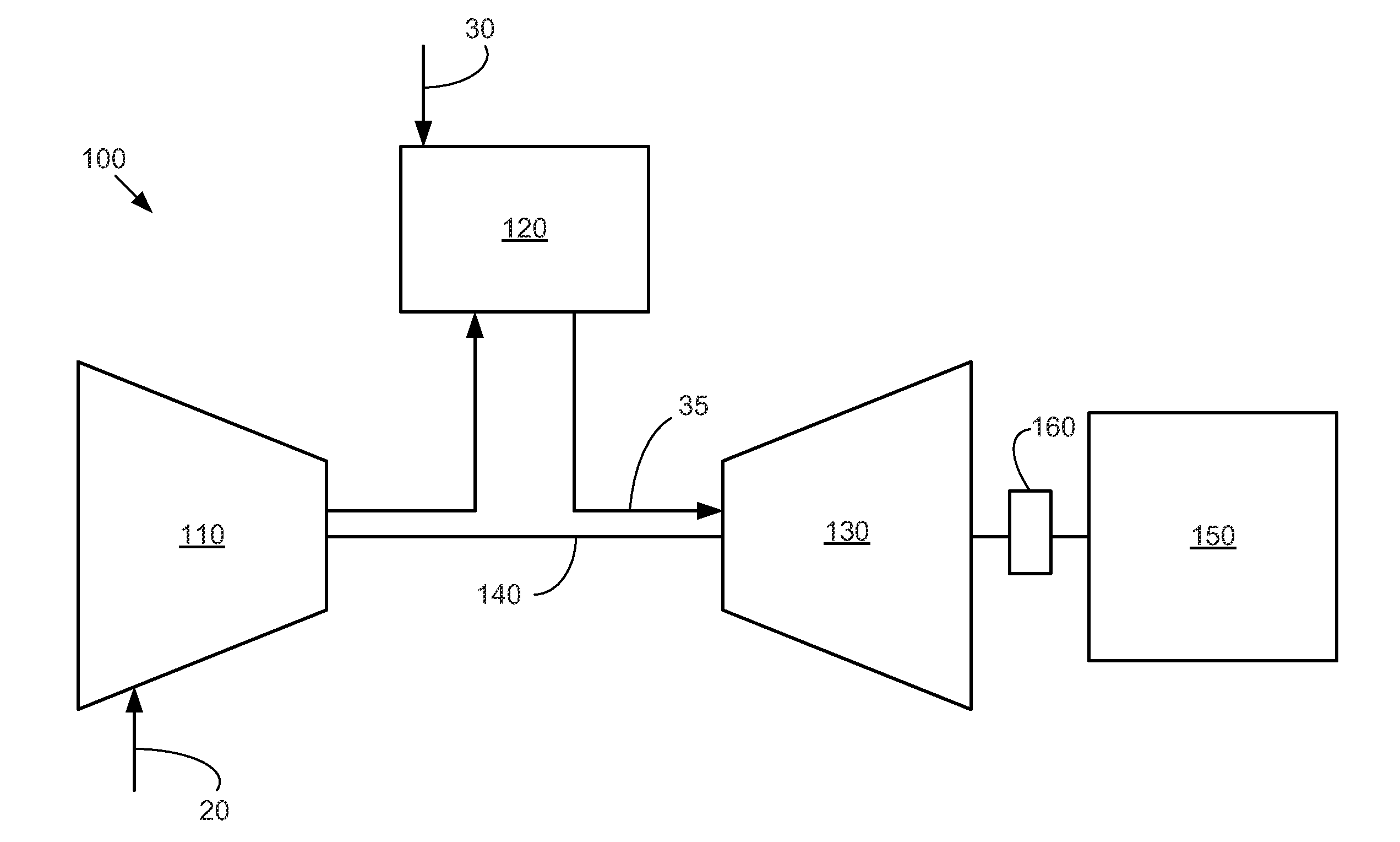
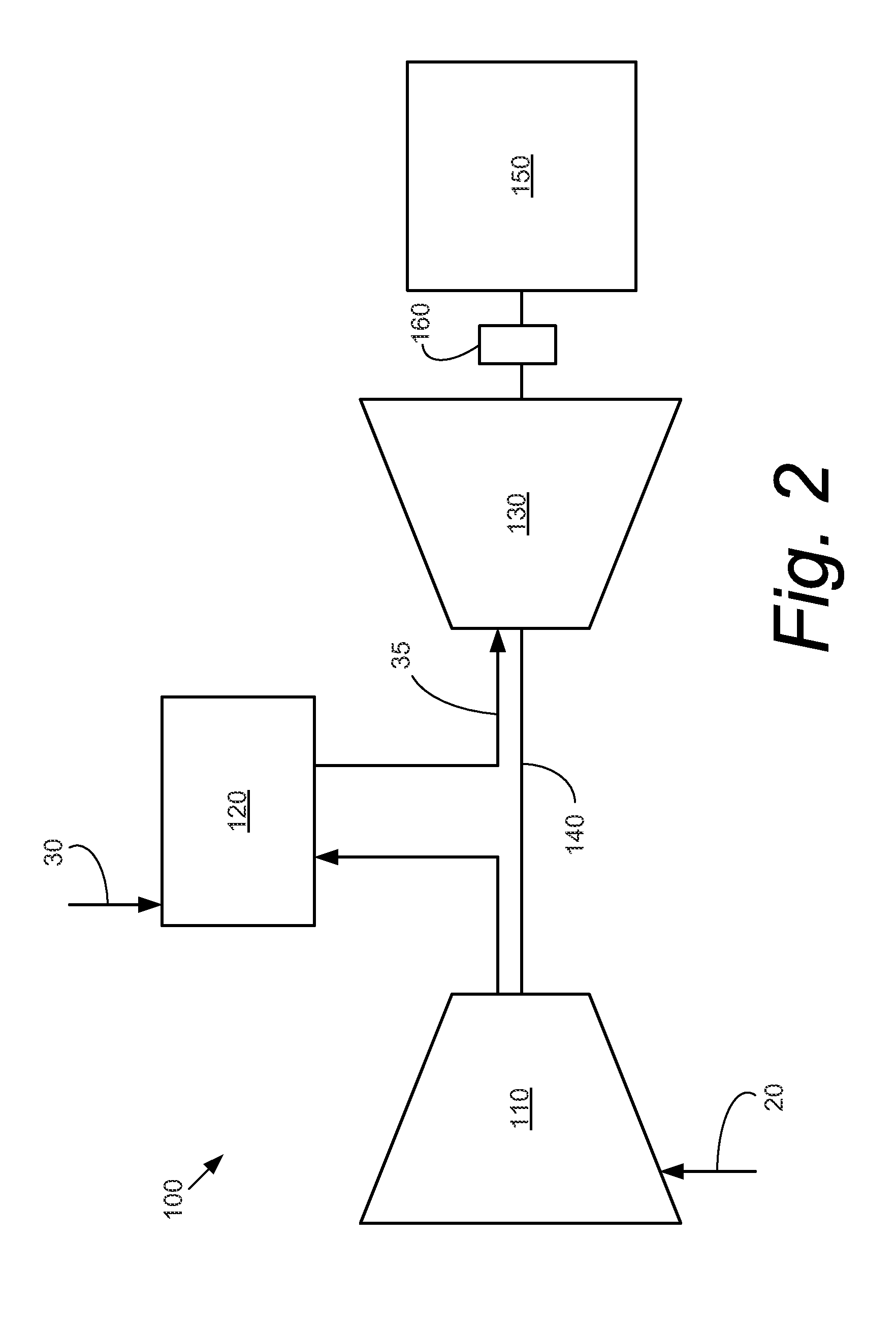
"The present patent describes a gas turbine engine generator system that includes a turbine, generator, and shaft. A torsional damping coupling is positioned about the shaft to limit the transmission of torque to the turbine during a generator based fault event. The system can generate torque during a fault event and damp the transmission of torque from the generator to the turbine using the torsional damping coupling. The technical effect of this patent is to improve the reliability and stability of gas turbine engine generators."

Problems solved by technology

These fault design requirements, however, may increase the overall size, cost, and weight of the turbine.
Shear couplings, however, generally do not provide any benefit during minor fault events and generally require replacement after a major fault event.
As such, shear couplings may be of limited effectiveness and long term value.

Method used


Image

  • Gas Turbine Engine Generator System with Torsional Damping Coupling
  • Gas Turbine Engine Generator System with Torsional Damping Coupling
  • Gas Turbine Engine Generator System with Torsional Damping Coupling

Examples


Embodiment Construction

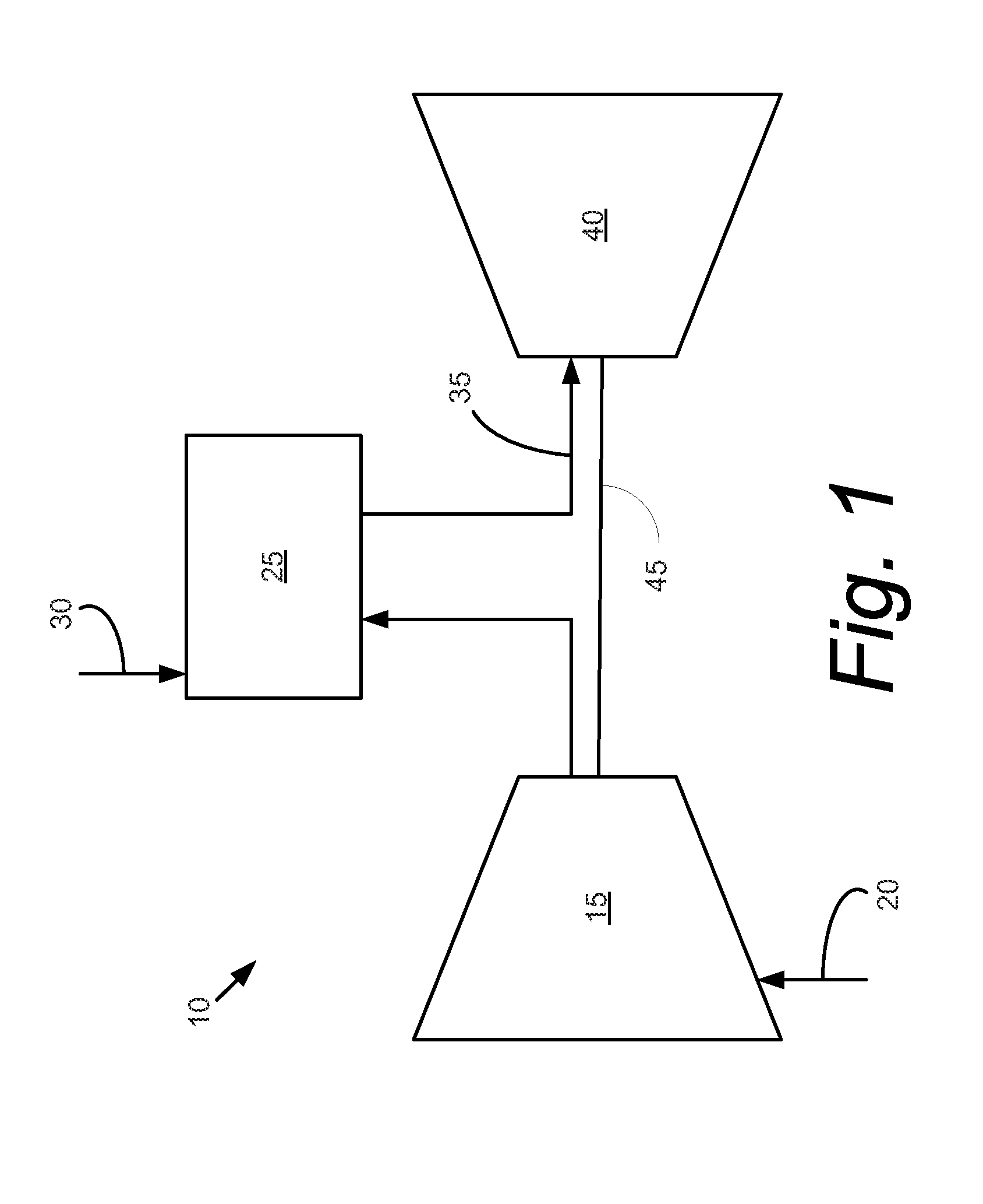
[0013]Referring now to the drawings, in which like numerals refer to like elements throughout the several views, FIG. 1 shows a schematic view of gas turbine engine 10 as may be used herein. The gas turbine engine 10 may include a compressor 15. The compressor 15 compresses an incoming flow of air 20. The compressor delivers the compressed flow of air 20 to a combustor 25. The combustor 25 mixes the compressed flow of air 20 with a compressed flow of fuel 30 and ignites the mixture to create a flow of combustion gases 35. Although only a single combustor 25 is shown, the gas turbine engine 10 may include any number of combustors 25. The flow of combustion gases 35 is in turn delivered to a downstream turbine 40. The flow of combustion gases 35 drives the turbine 40 so as to produce mechanical work. The mechanical work produced in the turbine 40 drives the compressor 15 via a shaft 45 and an external load such as an electrical generator and the like as will be described in more detai...


PUM


Abstract

The present application and the resultant patent provide a gas turbine engine generator system. The gas turbine engine generator system may include a turbine, a generator, and a shaft. The turbine drives the generator via the shaft. A torsional damping coupling may be positioned about the shaft so as to limit the transmission of torque to the turbine during a generator based fault event.

Description

TECHNICAL FIELD[0001]The present application relates generally to gas turbine engines and more particularly relates to the use of a torsional damping coupling between a gas turbine engine and a generator to protect the gas turbine engine from generator based fault events.BACKGROUND OF THE INVENTION[0002]Gas turbine engines and other types of turbo-machinery are often used to drive loads such as electrical generators. Gas turbines are designed to withstand certain levels of generator based fault events without damage. Such fault events may be defined as out-of-phase synchronizing, short circuits, and the like. Fault events may transmit high torques at high oscillation rates from the generator to the turbine. Generally described, a turbine may be designed to tolerate minor fault events without permanent damage and to tolerate major fault events without failure of the turbine. These fault design requirements, however, may increase the overall size, cost, and weight of the turbine.[0003...

Claims


Application Information

Patent Timeline
Patent Type & Authority Applications(United States)
IPC IPC(8): F16F15/133
CPCF01D15/10F02C7/36F16F15/16F16F15/1215F05D2260/96
Inventor SNOOK, DANIEL DAVIDSOMMERLATTE, KLAUS WERNER
Owner GENERAL ELECTRIC CO
Learn More