
Method for building magnetic core including laminations bound into packs for electrical machine

a technology of magnetic core and lamination, applied in the direction of lamination, ancillary operations, lamination, etc., can solve the problems of magnetic core damage, consequential increase, even significant, of power loss, etc., and achieve the effect of improving the energy efficiency of electrical machines, being easy and affordable to implemen

Active Publication Date: 2012-08-16
MARELLI EURO SPA
View PDF3 Cites 1 Cited by
  • Summary
  • Abstract
  • Description
  • Claims
  • Application Information

AI Technical Summary

Benefits of technology

[0012]One advantage of the method for building a magnetic core including laminations bound into packs for an electrical machine of the invention is that it does not require a very long time to make the magnetic core.
[0013]Another advantage of the method for building a magnetic core including laminations bound into packs for an electrical machine of the invention is that it is automated (i.e., it does not always require manual intervention by an operator).
[0014]Another advantage of the method for building a magnetic core including laminations bound into packs for an electrical machine of the invention is that it does not result in damaging the insulator between the laminations with a consequential increase, even significant, of losses of power due to eddy currents in the magnetic core during the operation of the electrical machine (i.e., a worsening of the energy efficiency of the electrical machine).
[0015]Another advantage of the method for building a magnetic core including laminations bound into packs for an electrical machine of the invention is that it is easy and affordable to implement.

Problems solved by technology

However, the building method proposed in U.S. Patent Application Publication 2010 / 154968A1 has various drawbacks because it requires a very long time to make the magnetic core, it may not be automated (i.e., it always requires manual intervention by an operator), and it could result in damaging the insulator between the laminations with a consequential increase, even significant, of losses of power due to eddy currents in the magnetic core during the operation of the electrical machine (i.e., a worsening of the energy efficiency of the electrical machine).

Method used

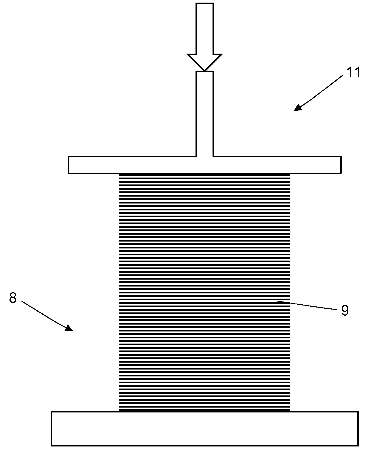
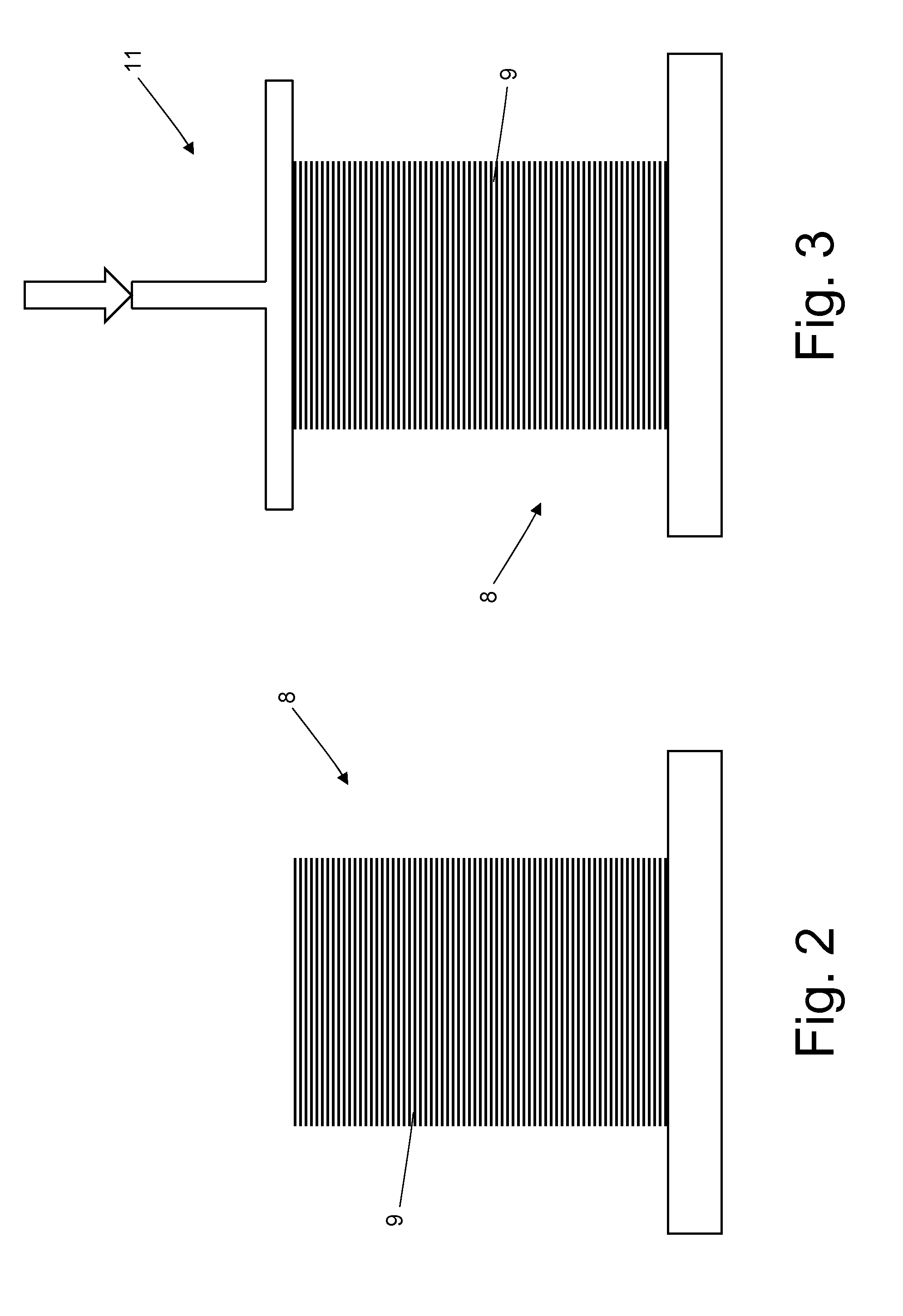

Image

  • Method for building magnetic core including laminations bound into packs for electrical machine
  • Method for building magnetic core including laminations bound into packs for electrical machine
  • Method for building magnetic core including laminations bound into packs for electrical machine

Examples


Embodiment Construction

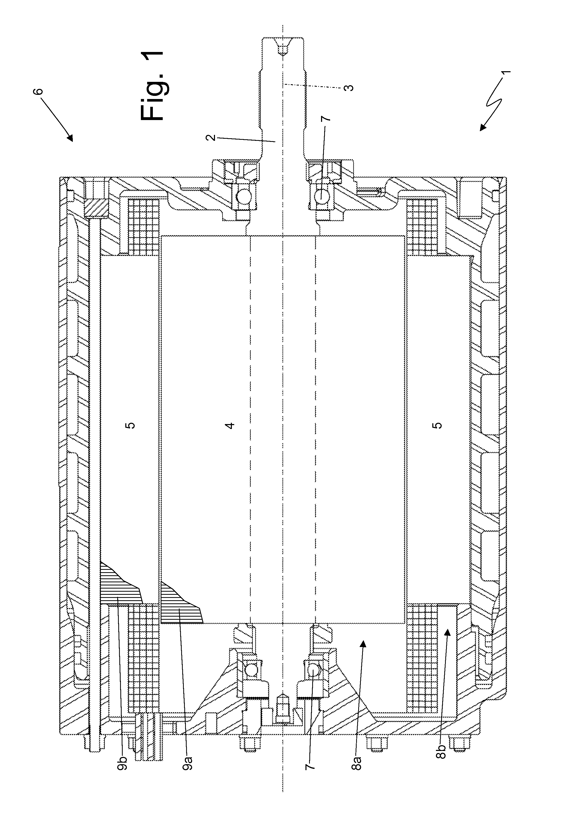
[0019]Numeral 1 in FIG. 1 indicates, as a whole, a synchronous electrical machine for auto-traction of reversible type (i.e., it may operate both as an electric motor by absorbing electrical power and generating a mechanical driving torque, and as an electric generator by absorbing mechanical energy and generating electrical power). The electrical machine 1 comprises a shaft 2, which is rotatably mounted to rotate about a central axis of rotation 3, a rotor 4 with cylindrical-shaped permanent magnets and keyed to shaft 2 to rotate together with shaft 2, and a cylindrical tubular stator 5 arranged about rotor 4 to enclose rotor 4 itself therein. Stator 5 is inserted inside a cylindrical casing 6 that is holed in the middle to allow one end of shaft 2 to come out from it, and accommodates a pair of bearings 7 that rotatably support shaft 2.

[0020]Rotor 4 comprises a cylindrical-shaped magnetic core 8a that consists of a plurality of overlapping laminations 9a bound into packs; the grou...


PUM

PropertyMeasurementUnit
axial lengthaaaaaaaaaa
thicknessaaaaaaaaaa
thicknessaaaaaaaaaa

Abstract

A method for building a magnetic core including laminations bound into packs for an electrical machine comprises steps of: stacking a group of laminations one on top of the other to build the core; binding into a pack the group building the core by locking members that axially compress the group with a predetermined clamping force; pre-compressing, before clamping the pack by the locking members, the group by a pre-compression press that is independent and separate from the locking members; measuring an axial length of the group while the group is being compressed by the pre-compression press; initially forming the group with a normally lacking number of laminations to initially have the measured length that is lower than or substantially equal to a desired length; and adding, after having completed pre-compression, an additional number of laminations to the group determined according to a difference between the desired and measured lengths.

Description

REFERENCE TO RELATED APPLICATION[0001]This application claims benefit of the filing date of and priority to Italian Patent Application BO2011A 000058 filed on Feb. 10, 2011.BACKGROUND OF INVENTION[0002]1. Field of Invention[0003]The invention relates to, generally, a method for building a magnetic core including laminations that are bound into packs for an electrical machine and, particularly, a rotating electrical machine for auto-traction.[0004]2. Description of Related Art[0005]Electric traction combined with traditional thermal traction to obtain hybrid traction is becoming increasingly popular in road vehicles. Electric traction requires the use of at least one rotating electrical machine that is normally reversible (i.e., that may operate both as electric motor by absorbing electrical power and generating mechanical driving torque, and as an electric generator by absorbing mechanical energy and generating electrical power) and is mechanically connected to the driving wheels of...

Claims


Application Information

Patent Timeline
Patent Type & Authority Applications(United States)
IPC IPC(8): B32B37/10
CPCH02K15/02Y10T29/49009Y10T29/49012
Inventor CIAMPOLINI, FRANCOGIORGIANNI, VINCENZOGIULIANI, PATRICK
Owner MARELLI EURO SPA
Learn More