
Round Baler

Active Publication Date: 2012-08-16
DEERE & CO
View PDF14 Cites 5 Cited by
  • Summary
  • Abstract
  • Description
  • Claims
  • Application Information

AI Technical Summary

Benefits of technology

[0008]The use of a fabric made from plastic fibers as a cover element guarantees a long service life of the cover element, because the fabric can be more easily folded or rolled up than single-piece, planar materials, such as tarps, and in this way also experiences less damage. Thus, a long service life of the cover element and low driving-power requirements for the movement of the cover element are achieved.
[0010]Furthermore, the fabric is advantageously permeable to air. In this way, in the interior of the baler, air flows generated by the rotating bale and the crop take-up device can flow out without a problem. Also, an undesired susceptibility to wind, particularly in the folded state, by the cover element is prevented.
[0011]In order to improve the stability of the device, several braces are provided that are coupled with the element at a distance from each other. In this way, the element, in the closed position, forms a polygon whose outline attaches to the approximately cylindrical bale chamber.
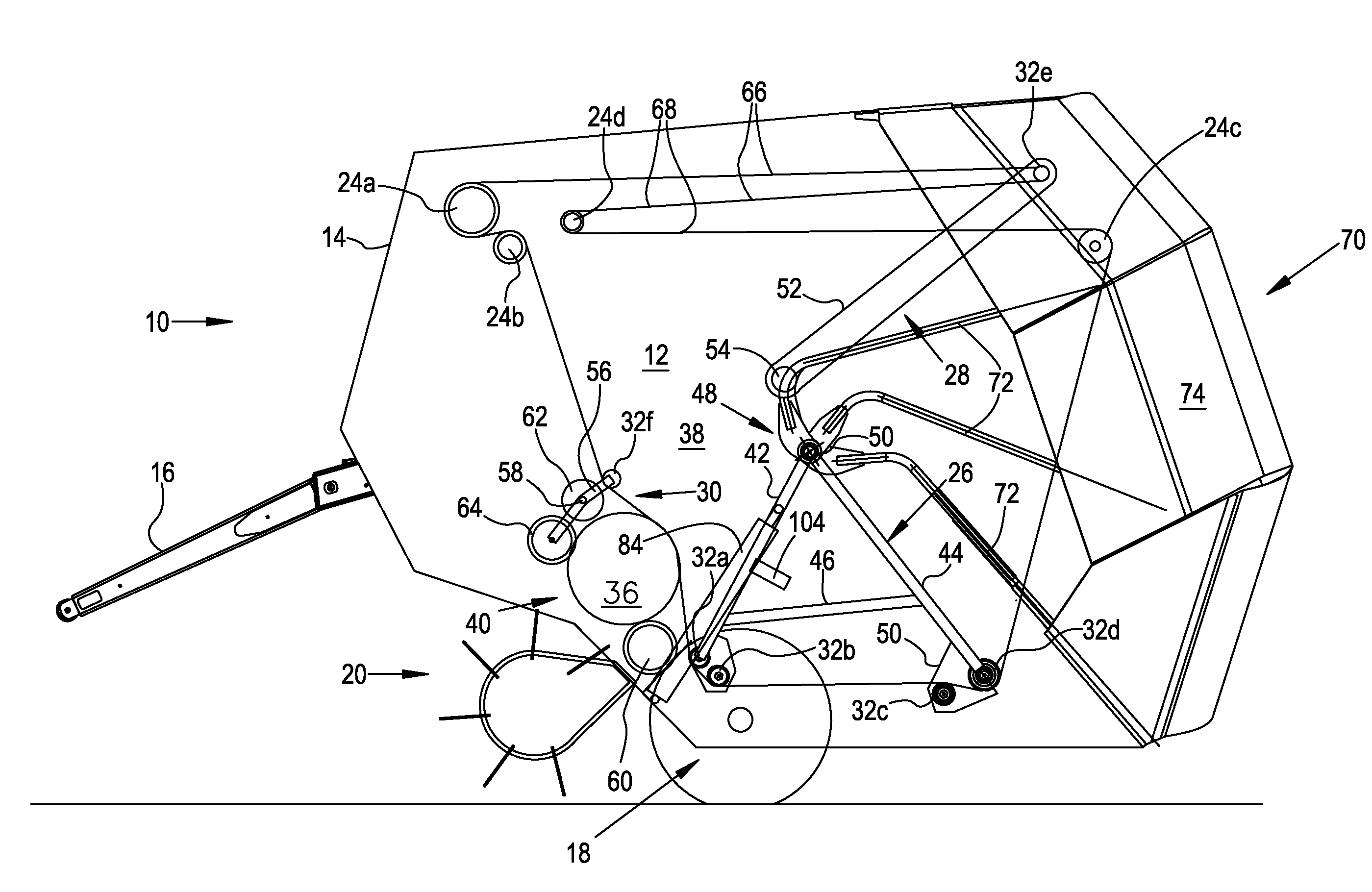
[0016]The described device is suitable especially for a round baler with a bale chamber and bale forming means supported by a carrier that can be moved for discharging a bale. Such a round baler is known from DE 102 50 425 A1. The device covers the bale chamber at the back, in order to prevent the risk of accidents and to shield the bale chamber from environmental effects.
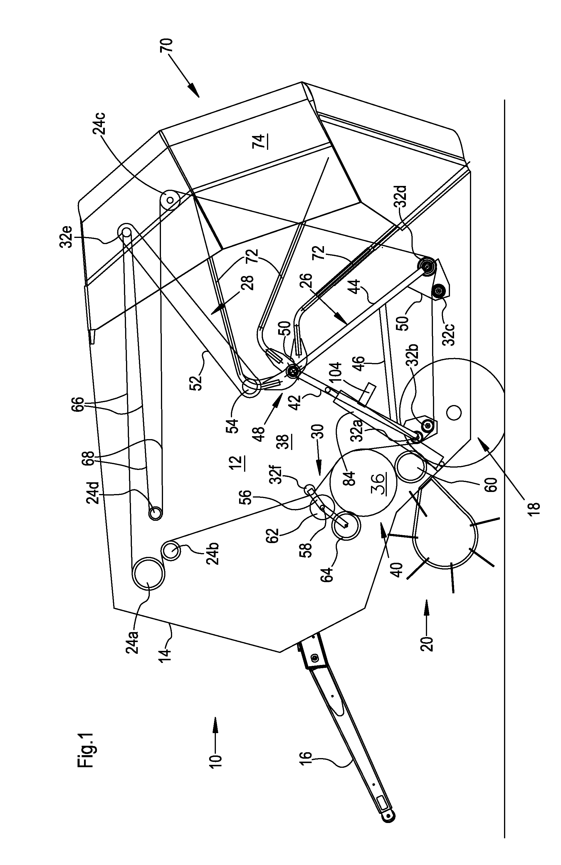
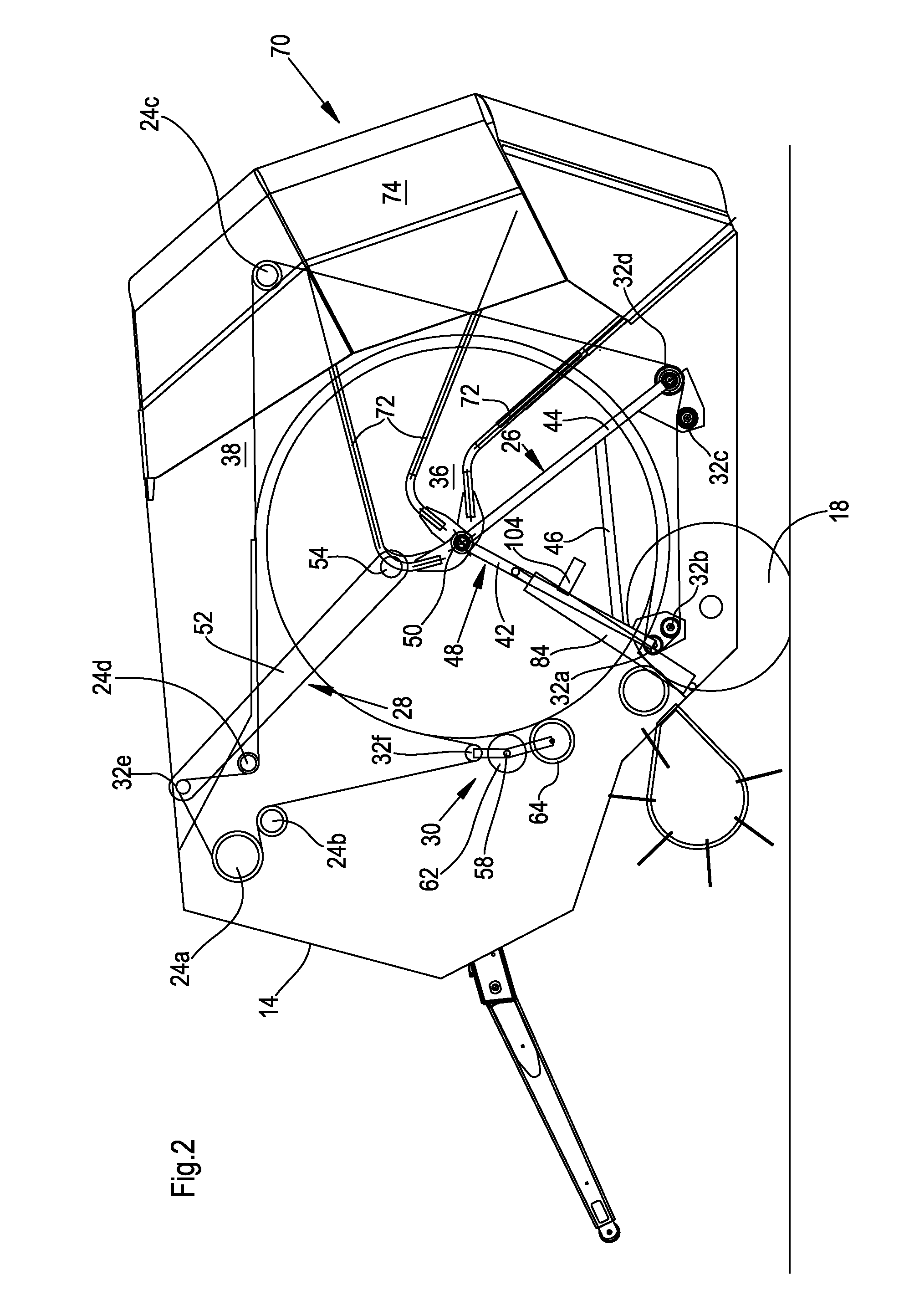
[0017]In a preferred embodiment, the (sole or lowermost) brace is locked in the lower, closed position on the frame of the round baler, in order to prevent an undesired opening of the cover element. During a movement for discharging a bale, the carrier first opens the lock and then transports the brace into the upper position. In this way, a separate drive for the brace is eliminated. After ejection of a completed bale, the carrier moves back into its bale-forming position. The brace is then led just by the force of gravity into the lower, closed position and is locked there automatically. In this way, damage to the device for covering the bale chamber is prevented even if, under the most unfavorable circumstances, a bale is still located in its range of motion. The pivoting axes of the carrier and the brace or braces are advantageously coaxial, but they could also be arranged at a spaced distance from each other. This embodiment is not limited to cover elements made from a fabric made of plastic fibers, but instead could be used with cover elements made from any materials.

Problems solved by technology

One disadvantage of the known protective device lies in that the material is subjected to considerable wear when it is wound or folded up.
In particular, tarps made from typical plastic material, such as those used, for example, for covering the truck beds of trucks, quickly form unattractive folds at which they later tear.

Method used


Image

  • Round Baler
  • Round Baler
  • Round Baler

Examples


Embodiment Construction

[0025]In FIG. 1 an embodiment of a round baler 10 is shown that has a frame 14 supported on a running gear 18. On the front side of the frame 14 there is a drawbar 16, for attaching the round baler 10 to a tractor and to pull it across a field. A take-up device 20 in the form of a Pick-Up is used for taking up crop lying on the ground, e.g., hay or straw laid in a swath. The crop taken up by the take-up device 20 is fed to the inlet of a bale chamber 12 and is rolled up there in a spiral shape into a round-cylindrical bale 36, bound, and then laid on the ground.

[0026]A lower, stationary roller 60 and two upper rollers 62, 64 are positioned at the inlet 40 of the bale chamber 20. The bale chamber 12 is further formed by an endless bale forming means 34 in the form of a belt that is guided about a plurality of stationary rotating bodies 24 and movable rotating bodies 32. While the bale chamber 12 is essentially surrounded by the bale forming means 34 on the periphery, it is closed on ...


PUM


Abstract

A device is provided for covering a bale chamber of a round baler. The device has a planar cover element made from a flexible material that extends between an upper holder and a brace moving between a lower, closed position, and an upper, open position for ejecting a round bale. The cover element consists of a fabric made from plastic fibers.

Description

FIELD OF THE INVENTION[0001]The invention relates to a device for covering a bale chamber of a round baler. The device is a planar cover element made from a flexible material that extends between an upper holder and a brace that can move between a lower, closed position and an upper, open position for ejecting a round bale. The invention also relates to a round baler equipped in this way.BACKGROUND OF THE INVENTION[0002]Round balers are used for producing bales made from stalk-like agricultural crops. Such round balers have a bale chamber and associated bale forming means. In typical round balers after completion of a bale, a rear door, on which rollers supporting or forming the bale forming means are mounted, is pivoted upward, in order to eject the bale.[0003]Various constructions of round balers have been proposed (see e.g. EP 1 308 078 A1) wherein carrier holding elements support the belt-shaped bale forming means in the lower region of the bale chamber of the round baler. The c...

Claims


Application Information

Patent Timeline
IPC IPC(8): A01F15/07B30B15/00
CPCA01F15/08
Inventor BEAUFORT, DAVID
Owner DEERE & CO
Learn More