Control unit and a method for controlling blade tip clearance

a control unit and blade technology, applied in the direction of machines/engines, engine starters, positive displacement liquid engines, etc., can solve the problems of presenting drawbacks, notably in cost, size, weight, and contact risk at this point of operation, and achieve the effect of reducing such drawbacks

Active Publication Date: 2012-08-09
SN DETUDE & DE CONSTR DE MOTEURS DAVIATION S N E C M A
View PDF4 Cites 20 Cited by
  • Summary
  • Abstract
  • Description
  • Claims
  • Application Information

AI Technical Summary

Benefits of technology

[0007]A main object of the present invention is thus to mitigate such drawbacks.

Problems solved by technology

There is thus a risk of contact at this point of operation, which point is referred to as the pinch point.
The use of an adjustable-position valve nevertheless presents drawbacks, in particular in terms of cost, of size, and of weight.

Method used


Image

  • Control unit and a method for controlling blade tip clearance
  • Control unit and a method for controlling blade tip clearance
  • Control unit and a method for controlling blade tip clearance

Examples


Embodiment Construction

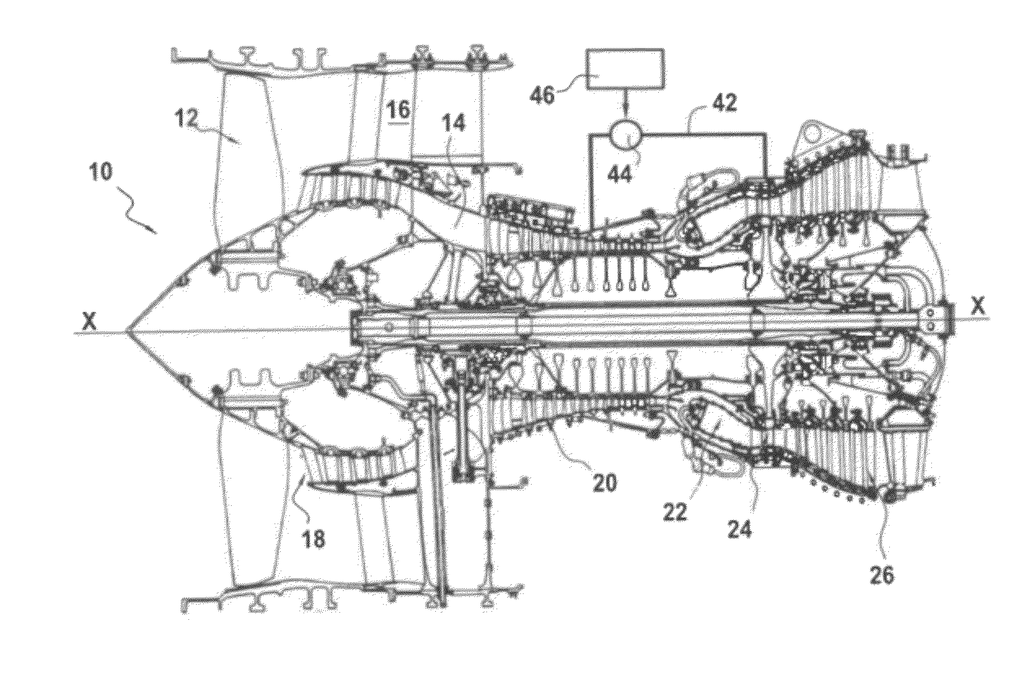
[0032]FIG. 1 is a diagrammatic view of a turbojet 10 of the bypass and two-spool type to which the invention applies in particular. Naturally, the invention is not limited to this particular type of gas turbine airplane engine.

[0033]In well-known manner, the turbojet 10 of longitudinal axis X-X comprises in particular a fan 12 that delivers a stream of air into a primary stream flow passage 14 and a secondary stream flow passage 16 that is coaxial around the primary stream passage. From upstream to downstream in the flow direction of the gas stream passing therethrough, the primary stream flow passage 14 comprises a low pressure compressor 18, a high pressure compressor 20, a combustion chamber 22, a high pressure turbine 24, and a low pressure turbine 26.

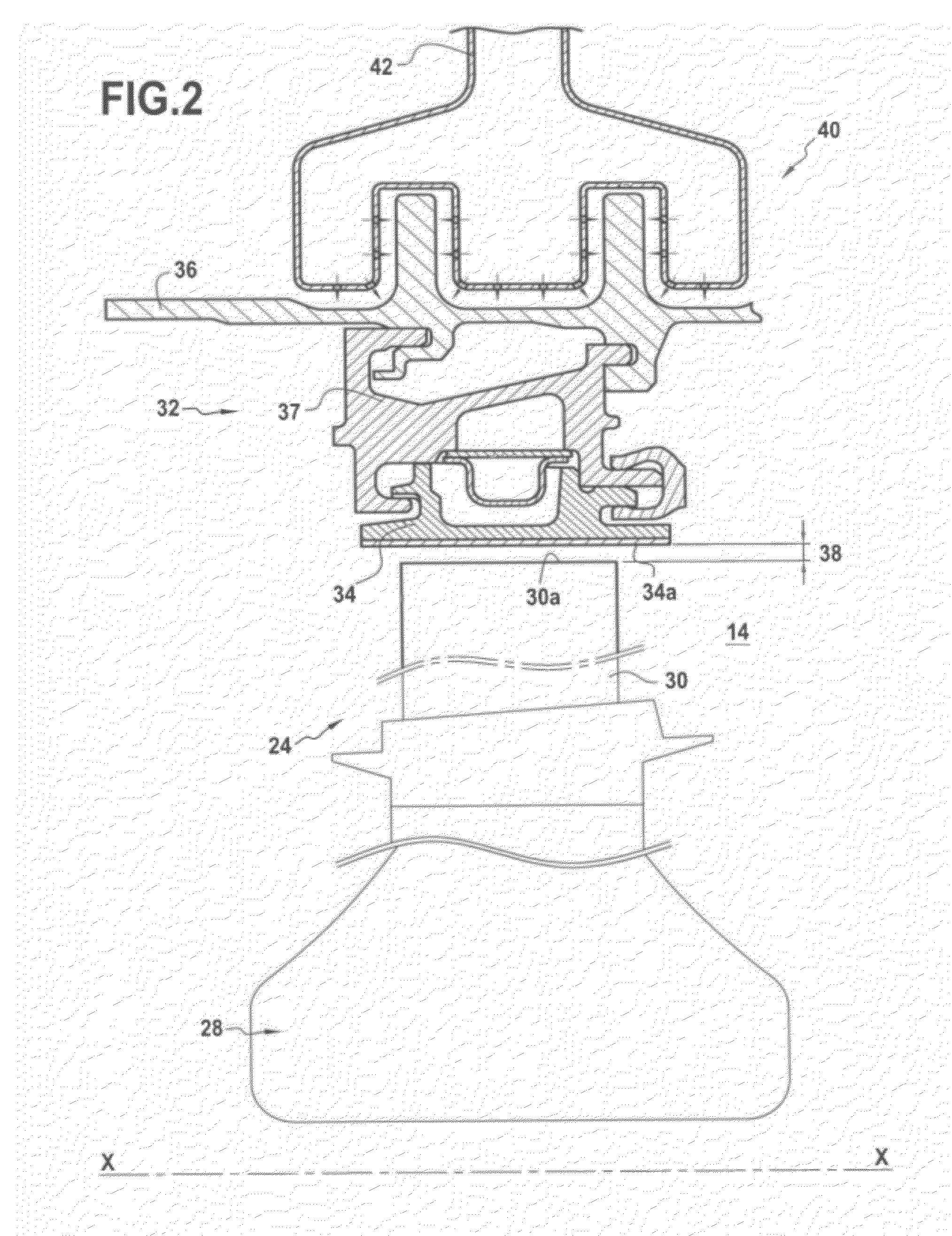
[0034]As shown more precisely in FIG. 2, the high pressure turbine 24 of the turbojet comprises a rotor made up of a disk 28 having a plurality of rotor blades 30 mounted thereon to extend into the primary stream flow passage 14. T...


PUM


Abstract

A method and system for controlling clearance between the tips of blades of a turbine rotor in a gas turbine airplane engine and a turbine ring of a casing surrounding the blades. A valve is controlled to act on a flow rate and/or a temperature of air directed against the casing. The valve is of the on/off type for switching between an open state and a closed state in a determined reaction time, the valve control module including a corrector for determining a first binary control signal that can take a first value corresponding to an open state and a second value corresponding to a closed state of the valve. The corrector includes a time-delay module for determining a binary control signal, with the duration between two successive changes of state in the control signal being not less than the reaction time of the valve.

Description

BACKGROUND OF THE INVENTION[0001]The present invention relates to the general field of turbomachinery for gas turbine aeroengines. It relates more particularly to controlling the clearance between the tips of moving blades of a turbine rotor and a turbine ring of an outlet casing surrounding the blades.[0002]The clearance that exists between the tips of the blades of the turbine and the ring that surrounds them depends on differences between the variations in the dimensions of the rotary portions (disk and blades forming the turbine rotor) and of the stationary portions (outer casing and the turbine ring that it includes). These variations in dimensions are both of thermal origin (associated with variations in the temperature of the blades, of the disk, and of the casing) and also of mechanical origin (in particular associated with the effect of the centrifugal force that acts on the turbine rotor).[0003]In order to increase the performance of a turbine, it is desirable to minimize ...

Claims


Application Information

Patent Timeline
Patent Type & Authority Applications(United States)
IPC IPC(8): F01D17/20
CPCF01D11/24
Inventor GAULLY, BRUNO ROBERTDJELASSI, CEDRIKMAROT, CECILE
Owner SN DETUDE & DE CONSTR DE MOTEURS DAVIATION S N E C M A
Why Eureka
Try Eureka