
DC blocking device by using impedance matching

a dc blocking and impedance matching technology, applied in the field can solve the problems of inability to study the miniaturization of dc blocking devices, and the difficulty in manufacturing strip-type dc blocking devices in small sizes, and achieve the effect of minimizing spatial constraints

Inactive Publication Date: 2012-08-09
ACE TECH
View PDF2 Cites 8 Cited by
  • Summary
  • Abstract
  • Description
  • Claims
  • Application Information

AI Technical Summary

Benefits of technology

[0029]The present invention provides the advantages of minimizing spatial constraints when mounting a DC blocking device into a mobile communication apparatus, and of achieving proper coupling even when the length of the area where coupling occurs in the DC blocking device is reduced.

Problems solved by technology

However, for the strip structure, there is a lack of study for miniaturization in a DC blocking device.
In this manner, since a length greater than or equal to ¼ of the wavelength corresponding to the used frequency needs to be obtained, there is difficulty in manufacturing the conventional strip-type DC blocking device in small sizes.

Method used


Image

  • DC blocking device by using impedance matching
  • DC blocking device by using impedance matching
  • DC blocking device by using impedance matching

Examples


Embodiment Construction

[0035]The DC blocking device using impedance matching according to certain embodiments of the invention will be described below in more detail with reference to the accompanying drawings.

[0036]FIG. 3 is a drawing illustrating an example of RF apparatus in which a DC blocking device using impedance matching according to an embodiment of the present invention is mounted.

[0037]Referring to FIG. 3, an RF apparatus in which a DC blocking device using impedance matching according to an embodiment of the present invention is mounted may include a first input connector 300, a second input connector 302, an output connector 304, a low band filter section 306, a high band filter section 308, a first DC blocking device 310 and a second DC blocking device 320.

[0038]The RF apparatus illustrated in FIG. 3 is a diplexer for filtering signals of both bands. The DC blocking device according to the present invention can be applied not only to filtering devices such as a diplexer, but also to various ...


PUM


Abstract

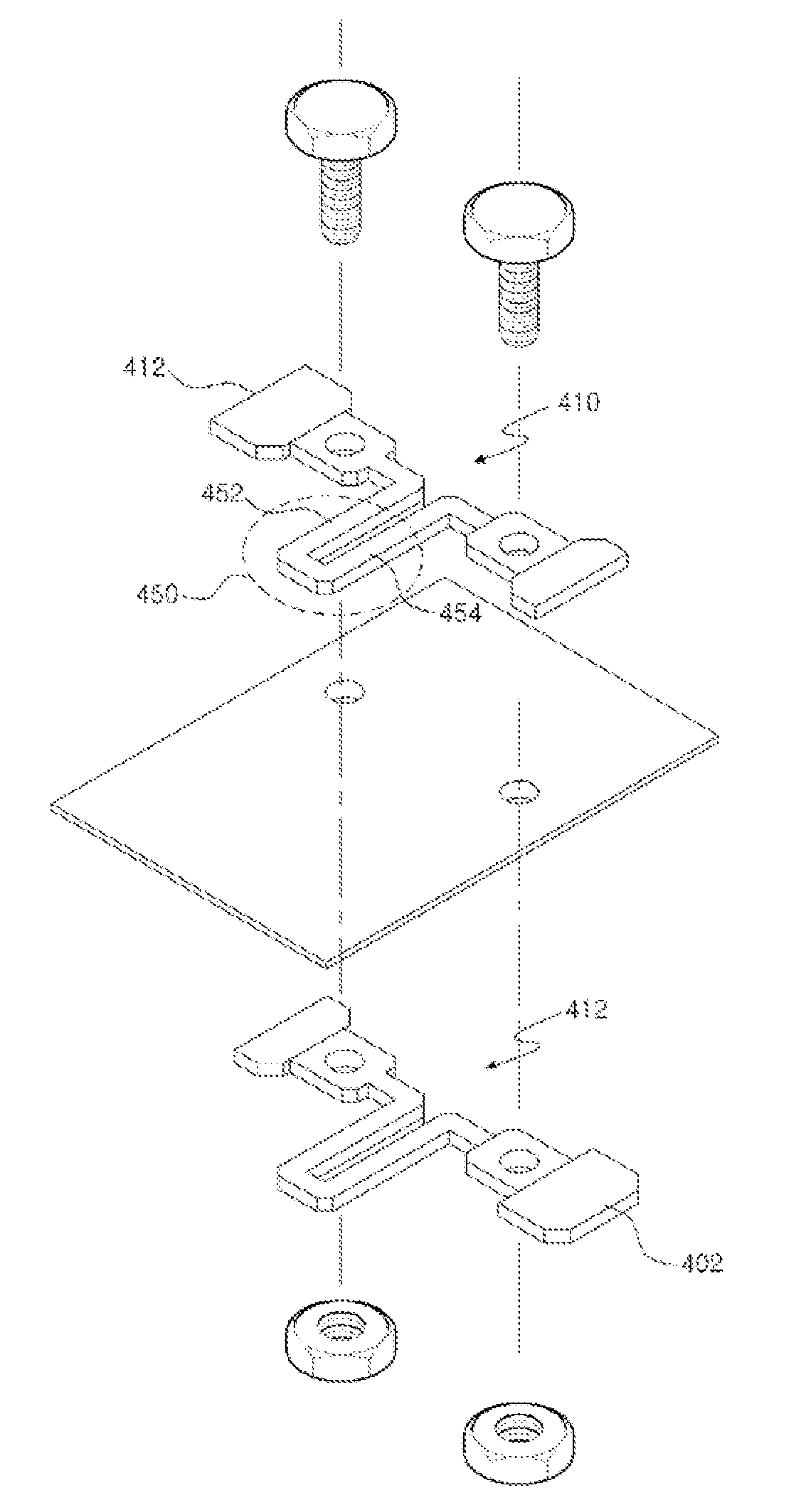
A DC blocking device using impedance matching is disclosed. The disclosed DC blocking device comprises: a first strip line configured to receive a signal and including a first line section and a first joining section joined to a part where a signal is received; and a second strip line separated from the first strip line at a designated distance and including a second line section and a second joining section for joining an output signal, where coupling occurs from the first strip line to the second strip line, the first strip line and the second strip line each have at least one bending section, and the first line section and the second line section have smaller line widths than the first joining section and the second joining section. The disclosed DC blocking device has the advantage of minimizing spatial constraints when it is installed in a mobile communication apparatus, and of achieving proper coupling even if the length of the part of the DC blocking device where coupling occurs is reduced.

Description

TECHNICAL FIELD[0001]The present invention relates to a DC blocking device, more particularly to a DC blocking device used in a mobile communication system.BACKGROUND ART [0002]DC blocking refers to eliminating DC components from signals and only passing frequency signals. Such DC blocking is required when DC signals are provided together with frequency signals for power supply in a device such as a mobile communication base station.[0003]The study of DC blocking has been concentrated mainly on two-line micro-strip structure and two-line strip structure.[0004]For the micro-strip structure, a DC blocking method using an inter-digital structure has been under study, for miniaturization of size and for broadening of the band. However, for the strip structure, there is a lack of study for miniaturization in a DC blocking device.[0005]The existing strip-type DC block has been interpreted in terms of an approximate equivalent circuit on the basis of the even / odd concepts suggested by LaCo...

Claims


Application Information

Patent Timeline
Patent Type & Authority Applications(United States)
IPC IPC(8): H03H7/38
CPCH01P1/20345H01P1/2007H01P1/203
Inventor JANG, JAE-WONCHUN, DONG-WAN
Owner ACE TECH
Learn More