
Measuring device for determining an operating state variable of a rotating structural element, in particular a bearing

a technology of rotating structural elements and measuring devices, which is applied in the direction of bearings, shafts, instruments, etc., to achieve the effects of reducing production costs, shortening life expectancy, and reducing life expectancy

Inactive Publication Date: 2012-08-09
SCHAEFFLER TECH AG & CO KG
View PDF4 Cites 4 Cited by
  • Summary
  • Abstract
  • Description
  • Claims
  • Application Information

AI Technical Summary

Benefits of technology

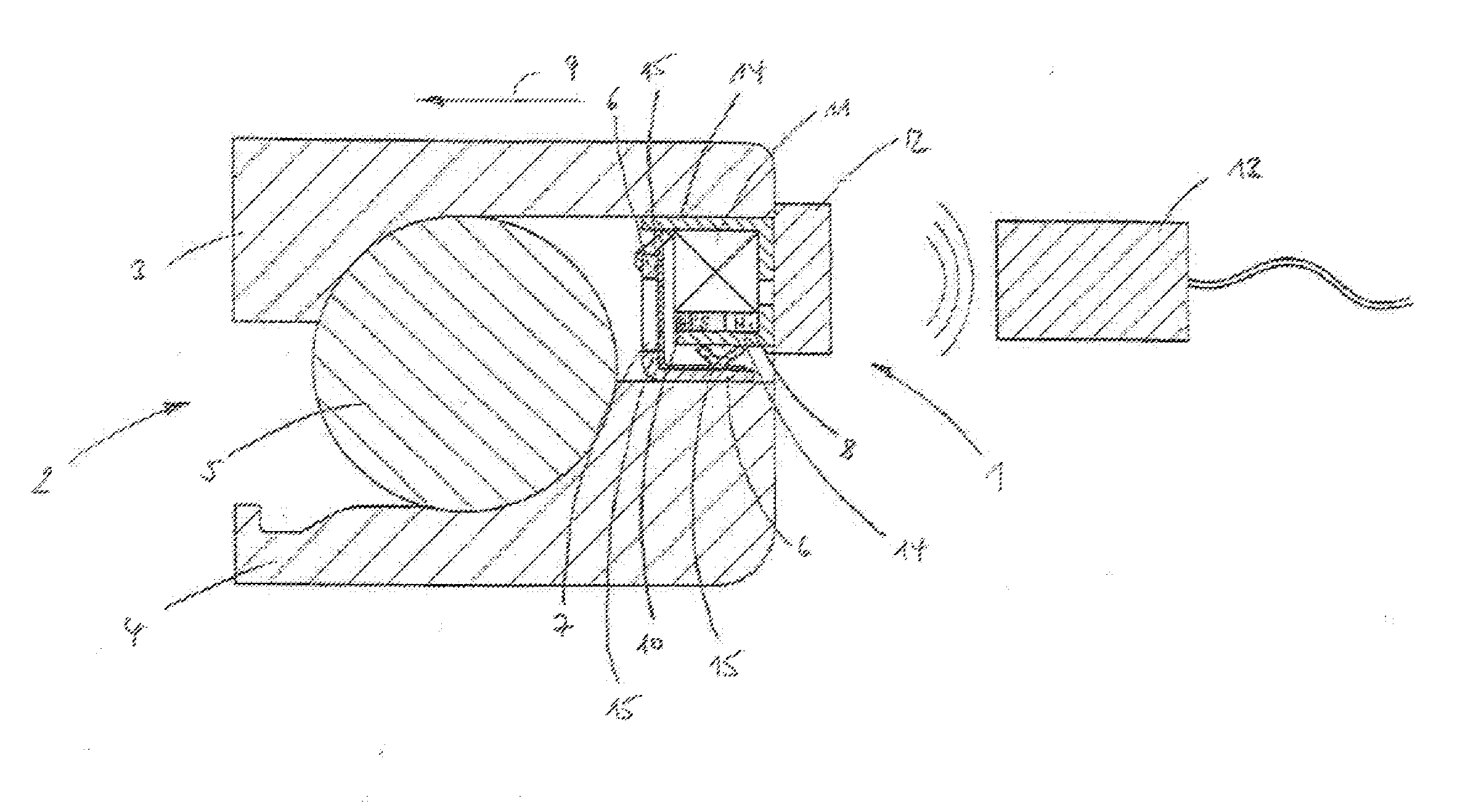
[0006]The measuring device, according to the present invention, serves to determine an operating state variable of a rotating structural element, in particular a bearing, and comprises a plurality of components. These components include a permanent magnet, an encoder ring for manipulating the magnetic field which is generated by the permanent magnet, a magnetic field sensor, a radio unit for transmitting measurement signals from the magnetic field sensor to an evaluation unit, and an energy converter unit for converting rotation energy into electrical energy. The encoder ring is produced from a ferromagnetic and non-premagnetized material as a result of which the associated production outlay and, therefore, the production costs are reduced relative to a design with pronounced and, in particular, alternating magnetization.
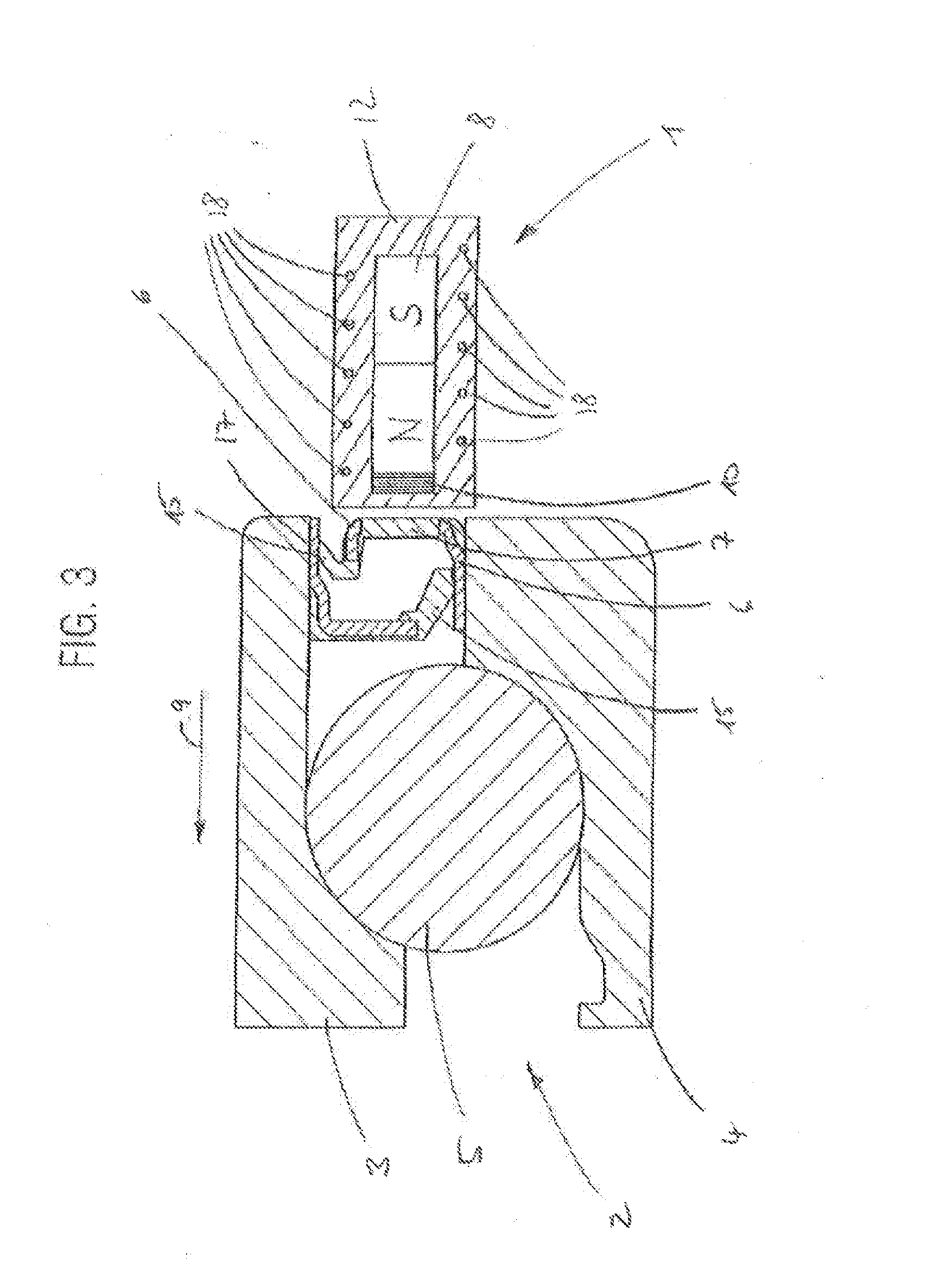
[0007]In one embodiment, the magnetic field sensor is fixed in position relative to the permanent magnet, whereas the encoder ring rotates together with the rotating structural element. In this way, magnetic biasing is defined in the region of the magnetic field sensor, a permanent magnetic field polarity being provided by the magnetic biasing independently of the operating state of the rotating structural element and therefore the rotary position of the encoder ring. Therefore, a movement of the encoder ring results in manipulation of the magnetic field, but not in reversal of the magnetic field polarity. This results, inter alia, in the operating point of the magnetic field sensor shifting, so that this can be chosen freely, and consequently expediently, by suitable selection of the configuration of the permanent magnet.
[0008]In another embodiment, at least one of the components of the measuring device, for example the radio unit and / or parts of the energy converter unit, which also include a power supply circuit and an intermediate energy storage means, are positioned in a housing or are injection-molded into a protective sheathing. Here, the housing or protective sheathing is designed in such a way that it moreover functions as a seal for the rotating structural element on account of a cover-like or cap-like shape. Therefore, both the component and the rotating structural element are protected, in particular against soiling, as a result of which both the structural element and the component are guaranteed a longer life expectancy. However, as an alternative, provision is also made of a cover-like seal with the component of the measuring device being fixed to the outside of the seal.
[0009]In accordance with a further refinement of the present invention, the magnetic field sensor is attached by means of a detachable connection, for example a screw connection, a plug connection or a clamping connection. This makes it possible for the magnetic field sensor, which typically has a shorter life expectancy than the other components of the measuring device, to be easily replaced.
[0010]The magnetic field sensor can also be a so-called active magnetic field sensor. The active magnetic field sensor is, for example, an XMR (X-magnetoresistive) sensor, a Hall sensor or an AMR (anisotropic magnetoresistive effect) sensor. Sensors of this kind are distinguished by a relatively simple structure and therefore favorable production costs.
[0013]In accordance with an alternative refinement, the permanent magnet used is a bar-like and, in particular, a single permanent magnet. Bar magnets of this kind can be produced with a particularly low level of outlay and are accordingly particularly advantageous in respect of cost.

Problems solved by technology

However, this considered to be disadvantageous since because the production costs are regarded as being excessively high.

Method used


Image

  • Measuring device for determining an operating state variable of a rotating structural element, in particular a bearing
  • Measuring device for determining an operating state variable of a rotating structural element, in particular a bearing
  • Measuring device for determining an operating state variable of a rotating structural element, in particular a bearing

Examples


Embodiment Construction

[0021]Mutually corresponding parts are provided with the same reference signs in all the figures.

[0022]In the exemplary embodiment described below, the measuring device 1 serves to detect the rotation movement of a shaft which is attached to a frame with the aid of a rolling bearing 2. The rolling bearing 2, which is designed as a single-row angular contact ball bearing, is shown in the form of a sectional illustration of a detail in FIG. 1. This angular contact ball bearing is constructed substantially from an external ring 3, an internal ring 4 and a number of spherical rolling bodies 5. The external ring 3 is connected to the frame by a bearing housing. The frame defines an inactive reference system in the usual way of viewing, even if the frame executes relative movements in relation to the earth system during operation. In contrast, the internal ring 4 is firmly connected to the shaft and executes variable rotation movements relative to the inactive reference system together wi...


PUM

PropertyMeasurementUnit
magnetic fieldaaaaaaaaaa
rotation energyaaaaaaaaaa
electrical energyaaaaaaaaaa

Abstract

A measuring device for determining an operating state variable of a rotating structural element, in particular a bearing, which has a plurality of components. Specifically, the measuring device has a permanent magnet, an encoder ring for manipulating the magnetic field which is generated by the permanent magnet, a magnetic field sensor, a radio unit for transmitting measurement signals from the magnetic field sensor to an evaluation unit, and an energy converter unit for converting rotation energy into electrical energy. The encoder ring is produced from a ferromagnetic and non-premagnetized material.

Description

CROSS-REFERENCE TO RELATED APPLICATION[0001]This application claims the priority of DE 10 2011 003 703.9 filed Feb. 7, 2011, which is incorporated by reference herein.FIELD OF THE INVENTION[0002]The invention relates to a measuring device for determining an operating state variable of a rotating structural element, in particular a bearing.BACKGROUND OF THE INVENTION[0003]Operating state variables which describe the rotation movement of the rotating structural element, such as rotary position, angular speed, angular acceleration etc., are of particular interest in the present case. Therefore, the invention relates primarily to a measuring device which detects at least one operating state variable which describes the rotation movement.[0004]A measuring device for identifying rotation is disclosed in European Patent Specification EP 1 342 633 B1. The measuring device comprises a current generator, which has a stator and a rotor, a power supply circuit and a magnetic field sensor. In th...

Claims


Application Information

Patent Timeline
Patent Type & Authority Applications(United States)
IPC IPC(8): G01N27/82
CPCF16C41/007F16C41/004F16C41/008G01P3/443F16C19/163F16C33/723F16C33/7883F16C2300/02
Inventor MOCK, CHRISTIANHEIM, JENSKOENIGER, FLORIAN
Owner SCHAEFFLER TECH AG & CO KG
Learn More