Electric micromotor

a miniature motor and electric motor technology, applied in the direction of dynamo-electric machines, electrical apparatus, dc commutators, etc., can solve the problems of difficult to realize a low speed actuation or even a rotational position regulation with such miniature motors, and the known configurations are not suitable for generic miniature motors, so as to achieve secure detection of the rotational position of the rotor and great exactness

Active Publication Date: 2012-08-09
DR FRITZ FAULHABER
View PDF6 Cites 2 Cited by
  • Summary
  • Abstract
  • Description
  • Claims
  • Application Information

AI Technical Summary

Benefits of technology

[0013]It is accordingly provided according to the invention that a sensor chip in the form of at least one magnetic field sensor is arranged in such a way in an area which is axially adjacent to the front face of the magnetic rotor located within a plane that is vertical to the rotational axis is provided for the purpose of detecting the rotational position of the magnetic rotor. The magnetic field sensor is impinged by the magnetic field of the magnetic rotor in such a way that the magnetic field can be evaluated in order to determine the rotational position of the rotor. The magnetic field, that is, the stray field of the magnetic rotor, can thus be advantageously directly detected and evaluated by means of the invention without any additional transmitter elements, in order to detect the rotational position of the magnetic rotor. The sensor chip preferably includes several, and namely at least three, but preferably four individual magnetic field sensors, in particular Hall-effect sensors, integrated in one component. The positioning and alignment of the magnetic field sensors relative to the magnetic rotor is in this way also possible with great exactness within the very small motor; the standard sensor chip only needs to be mechanically positioned on the stator relative to the magnetic rotor.
[0014]The sensor chip can be configured with a very flat design, and in particular as a single chip encoder, which comprises a signal evaluation as IC component, which is such that it directly delivers, in addition to the magnetic field sensors, an absolute and / or incremental rotational position signal for an external electronic control system. In this way, the electronic control system can also be designed, in addition to the actual commutation, for the exact regulation of the rotor position and / or also for the adjustment of low rotor speeds. The actuation of the motor can thus be optimally commutated from a standstill across the entire speed range, which would not be possible by means of a synchronic control or with a sensorless control utilizing the back EMF induced voltage in the stator coils. The actuation of the motor can even take place with sinus commutation due to the available output signals of the preferred single chip encoder, which was not possible until now with this type of small motors.
[0015]It is furthermore advantageous if the magnetic field sensors integrated into the sensor chip are arranged in an area that covers the axial projection of the magnetic rotor and in a specific peripheral distribution over a reference circle around the extended rotational axis, wherein the reference circle has a diameter that is located in the area between the diameter of the rotor shaft, which corresponds to the inner diameter of the magnetic rotor, and the outer diameter of the magnetic rotor. It is particularly advantageous if the diameter of the reference circle on which the magnetic field sensors are arranged is located within the outer half of the annular cross section of the magnetic rotor. The sensor chip can furthermore be arranged very close to the magnetic rotor. The sensor chip should be spaced from the adjacent front face of the magnetic rotor via an axial gap, which corresponds to a maximum of 1 to 1.5 times the diameter of the reference circle of the magnetic field sensors. It has been shown that a secure detection of the rotational position of the rotor is possible based only on the magnetic field of the rotor by means of this described configuration and arrangement of the sensor chip, and thus without additional transmitter elements, such as in particular separate transmitter magnets.

Problems solved by technology

It is thus difficult to realize an actuation at low speeds or even a rotational position regulation with such miniature motors.
All these known configurations are not suitable for a generic miniature motor of the kind discussed herein due to their extremely small overall size, with an outer diameter that must in any case be smaller than / equal to 6 mm.
The actuation of the motor can even take place with sinus commutation due to the available output signals of the preferred single chip encoder, which was not possible until now with this type of small motors.

Method used


Image

  • Electric micromotor
  • Electric micromotor
  • Electric micromotor

Examples


Embodiment Construction

[0026]With regard to the following description, it is expressly emphasized that the invention is not limited to the exemplary embodiment, and therefore not to all or several features of the described feature combinations, but that each individual partial feature of the exemplary embodiment has an inventive importance per se, separately from all others, with the partial features described in connection therewith.

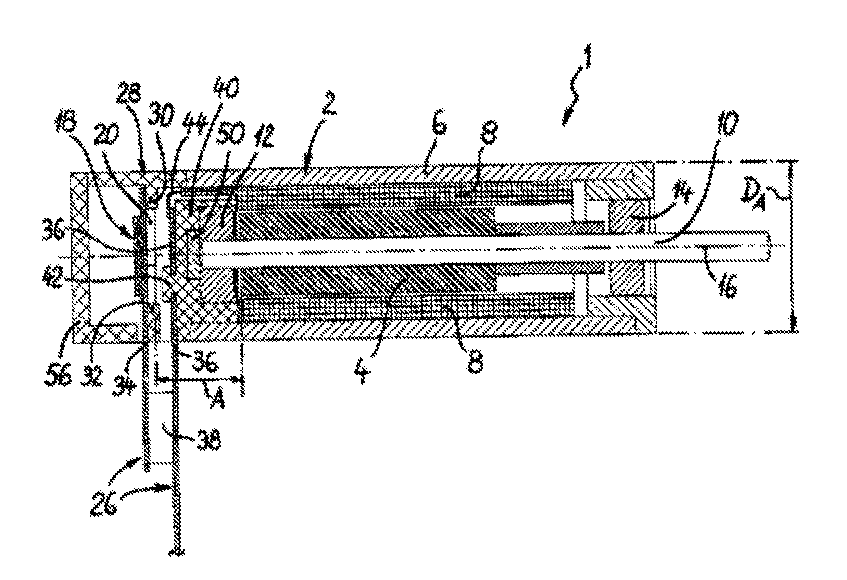
[0027]As can be seen first of all in FIG. 1, a miniature electric motor 1 according to the invention is comprised of a hollow cylindrical stator 2 and a permanent magnetic rotor 4. The miniature motor 1 or its stator 2 has an outer diameter DA, which is smaller than or equal to 6 mm, in particular even smaller than or equal to 5 mm. The stator 2 has an outer hollow cylindrical return path element 6 made from soft magnetic material, a so-called iron yoke, and stator coils 8 accommodated inside the return path element 6. The cylindrical magnetic rotor 4 is seated on a rotor sha...


PUM


Abstract

A miniature electric motor (1) with an outer diameter (DA) that is smaller than about 6 mm, having a hollow cylindrical stator (2) with stator coils (8) and a magnetic rotor (4) rotatably arranged around a rotational axis (16) in the stator (2) by rotor shaft (10). The stator coils (8) can be energized in order to generate a magnetic rotational field in dependence upon the rotational position of the magnetic rotor (4). To detect the rotational position of the magnetic rotor (4), a sensor chip (20) having at least one magnetic field sensor (22) is arranged in an area axially adjacent to a front face of the magnetic rotor (4) located within a plane that is vertical to the rotational axis (16). The magnetic field sensor (22) is impinged by the magnetic field of the magnetic rotor (4) so that the rotational position of the rotor can be evaluated.

Description

CROSS REFERENCE TO RELATED APPLICATION[0001]This application claims priority to German Patent Application No. 20 2011 002 402.4, filed Feb. 4, 2011.FIELD OF THE INVENTION[0002]This invention concerns a miniature electric motor with an outer diameter smaller than / equal to 6 mm, consisting of a hollow cylindrical stator with stator coils and a magnetic rotor arranged so as to rotate around a rotational axis in the stator by means of a rotor shaft, wherein the stator coils can be driven in dependence upon the rotational position of the magnetic rotor in order to generate a magnetic rotating field.BACKGROUND AND SUMMARY OF THE INVENTION[0003]Miniature motors of the above-referenced type are frequently brushless direct current motors, which are also called BLDC motors (BLDC=brushless direct current). Because of their very small overall size with an outer diameter of only a maximum of 6 mm, the determination of the rotational rotor position, which is required for commutation control, take...

Claims


Application Information

Patent Timeline
Patent Type & Authority Applications(United States)
IPC IPC(8): H02K11/00
CPCH02K29/08
Inventor WALLNER, HERBERT
Owner DR FRITZ FAULHABER
Why Eureka
Try Eureka