
Image processing apparatus and profile generation method

Active Publication Date: 2012-08-02
CANON KK
View PDF23 Cites 6 Cited by
  • Summary
  • Abstract
  • Description
  • Claims
  • Application Information

AI Technical Summary

Benefits of technology

[0011]The present invention is made to solve the foregoing problem; an object of the present invention is to provide an image processing apparatus and a profile generation method that prevent, when gamut mapping is performed, lightness jumping regardless of the shape of the color gamut of an input device and that can perform satisfactory color reproduction.
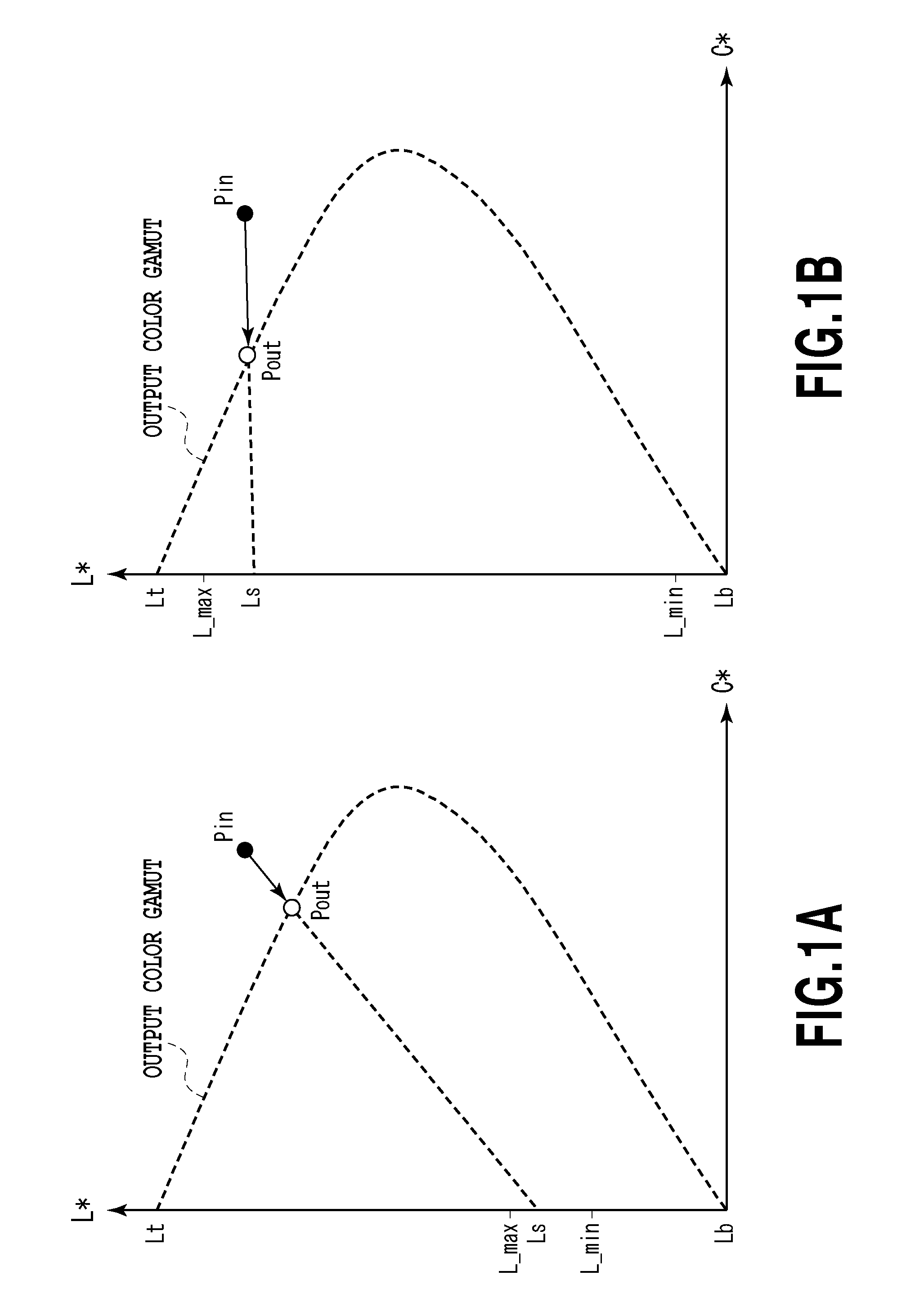
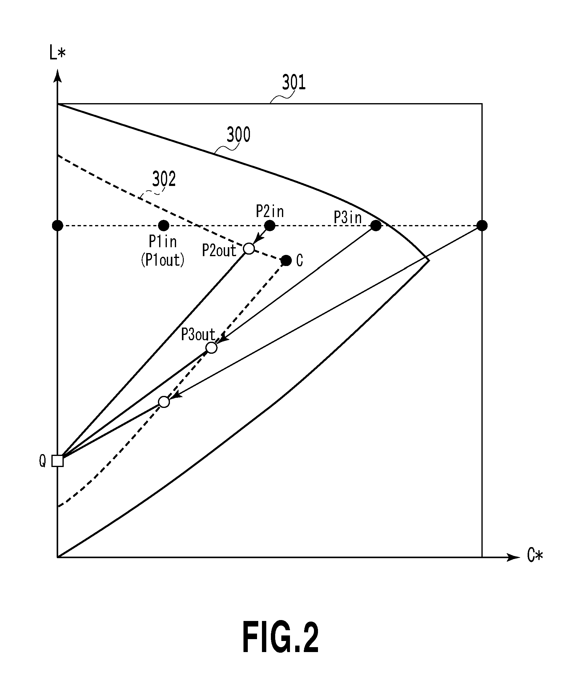
[0014]According to the configuration described above, whether or not the color of the grid point to be mapped is present in the first division region where, in the plane of the hue of the color of the grid point, the color has a lightness higher than the lightness of the maximum chroma point in the second color gamut that is for example a color gamut of the output device and has a chroma higher than the chroma of the maximum chroma point is determined. Then, when the color of the grid point is present in the first division region, the focal color is set at a position that has a lightness equal to or higher than the lightness of the intersection of the straight line connecting the color of the grid point to the maximum chroma point and the achromatic axis, and the color of the grid point is mapped. In this way, it is possible to prevent the separation of the output color corresponding to the grid point into a color on the higher lightness side and a color on the lower lightness side with respect to the maximum chroma in the second color gamut, that is, the occurrence of significant difference in lightness.

Problems solved by technology

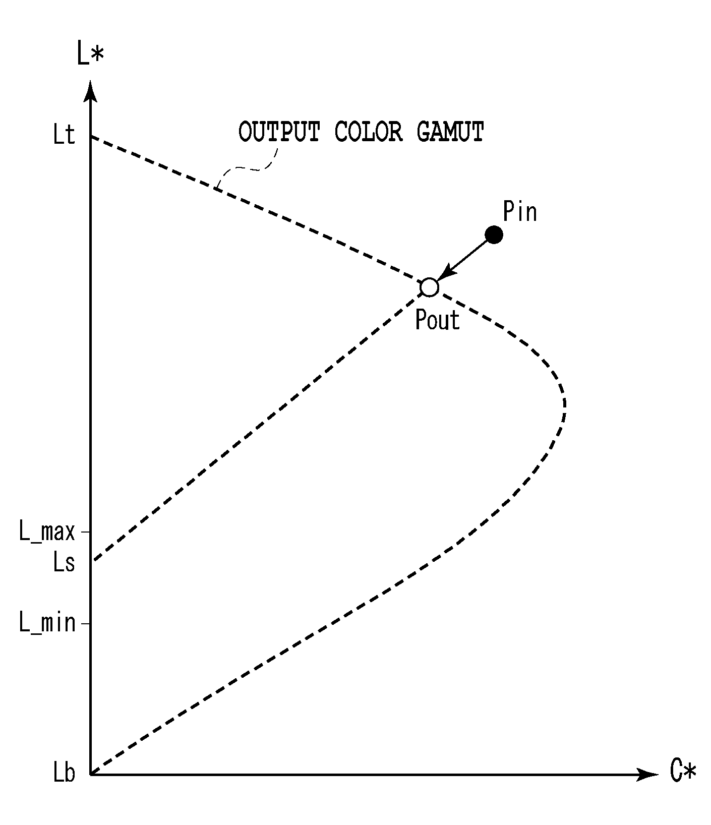
However, in the mapping using the focal color as disclosed in Japanese Patent Laid-Open No. 2007-274584, a large change of lightness that is called “lightness jumping” may occur depending on the shape of the color gamut of an output device, and consequently, the impression on a color reproduced in an input device disadvantageously appears to be different from that on a color reproduced in the output device.

Method used


Image

  • Image processing apparatus and profile generation method
  • Image processing apparatus and profile generation method
  • Image processing apparatus and profile generation method

Examples


first embodiment

[0026]The first embodiment of the present invention relates to an apparatus and a method that generate a profile for mapping, in a standard color space, the color gamut of an input device to the color gamut of an output device.

(Configuration of Image Processing Apparatus)

[0027]FIG. 3 is a block diagram showing the configuration of an image processing apparatus according to the present embodiment. The image processing apparatus of the present embodiment is realized through the execution of a program by a host computer. In FIG. 3, a CPU 500 performs, according to information data and various programs stored in a ROM 501, various types of control on a RAM 502, an operation portion 503, an image processing portion 504, a monitor 505, an image input device 506 and an image output device 507. Examples of the programs stored in the ROM 501 include a control program, an OS (operating system), an application program, a color conversion processing module and a device driver. An information st...


PUM


Abstract

When a grid point that is the object to be mapped is present in a first division region a color of which has lightness equal to or higher than the lightness at the maximum chroma point in the color gamut and has chroma higher than the chroma at that point, the intersection of a straight line connecting the grid point to the maximum chroma point and an achromatic axis is calculated and a point having lightness equal to or higher than the lightness of the intersection is set as the focal color. Then, the intersection of a straight line connecting the object grid point to the focal color and the boundary of color gamut is set as an output color for the grid point. The output colors are prevented from being separated into color on the high and on the low lightness sides with respect to the maximum chroma point.

Description

BACKGROUND OF THE INVENTION[0001]1. Field of the Invention[0002]The present invention relates to an image processing apparatus and a profile generation method. More specifically, the invention relates to gamut mapping in which color gamut of an input device is converted into a color gamut of an output device.[0003]2. Description of the Related Art[0004]In the so-called color management system (CMS) or the like for realizing a color reproduction technology that does not depend on a device between input-output devices, a gamut mapping technology that absorbs a difference in color reproduction range between the input-output devices is used. Conventionally, as one method of gamut mapping, an algorithm of mapping to a point on an auxiliary line that is drawn to one point fixed on a lightness axis (for example, L*=50, a color represented by this point is hereinafter referred to as a focal color) is known.[0005]Japanese Patent Laid-Open No. 2007-274584 discloses an example of gamut mapping...

Claims


Application Information

Patent Timeline
IPC IPC(8): G06K9/00
CPCH04N1/6058H04N1/603
Inventor MIYAZAKI, SHINICHIKISHINO, MAYUKOMIYAZAKI, TOSHIKI
Owner CANON KK
Learn More