
Driving assistant method and system for electric vehicle

a technology for electric vehicles and assistants, applied in the direction of process and machine control, navigation instruments, instruments, etc., can solve the problems of affecting the willingness of the driver to use electric vehicles, no charging station is located within the maximum driving region, and inconvenient for drivers, etc., to achieve flexible driving path selection

Active Publication Date: 2012-08-02
IND TECH RES INST
View PDF8 Cites 70 Cited by
  • Summary
  • Abstract
  • Description
  • Claims
  • Application Information

AI Technical Summary

Benefits of technology

[0009]The disclosure is directed to a driving assistant method and system for an electric vehicle, which is capable of displaying a regional guidance to provide a user more flexible driving path selections.
[0010]The disclosure is directed to a driving assistant method and system for an electric vehicle, by which when the electric vehicle is started up, a battery energy safe driving region is calculated, and is dynamically presented to a user through a user interface. In this way, a problem that none charging station and none battery exchange station are located around when the battery of the electric vehicle is required to be charged is avoided.
[0011]The disclosure is directed to a driving assistant method for an electric vehicle, and a driving assistant system for the electric vehicle, which can effectively use electricity supplying equipment information, electricity supplying status and real-time information to provide a suitable electricity supplying planning for a driver, and provide a flexible driving suggestion according to driver's demand.

Problems solved by technology

A plurality of applicable methods has been provided for charge navigation, though in these methods, real-time information (for example, traffic status, path and destination planning, etc.), driver's demand, electricity supplying equipments and geographic information are not considered, and the driver of the electric vehicle has to make a concession to a planning result of electricity supplying equipment navigation in order to facilitate battery charging, battery exchange to improve the battery life, which causes inconvenience to the driver, and also affects willingness of the driver of using the electric vehicle.
However, when it is discovered that the remained battery energy is less than the predetermined value, it is possible that none charging station is located within the maximum driving region.

Method used


Image

  • Driving assistant method and system for electric vehicle
  • Driving assistant method and system for electric vehicle
  • Driving assistant method and system for electric vehicle

Examples

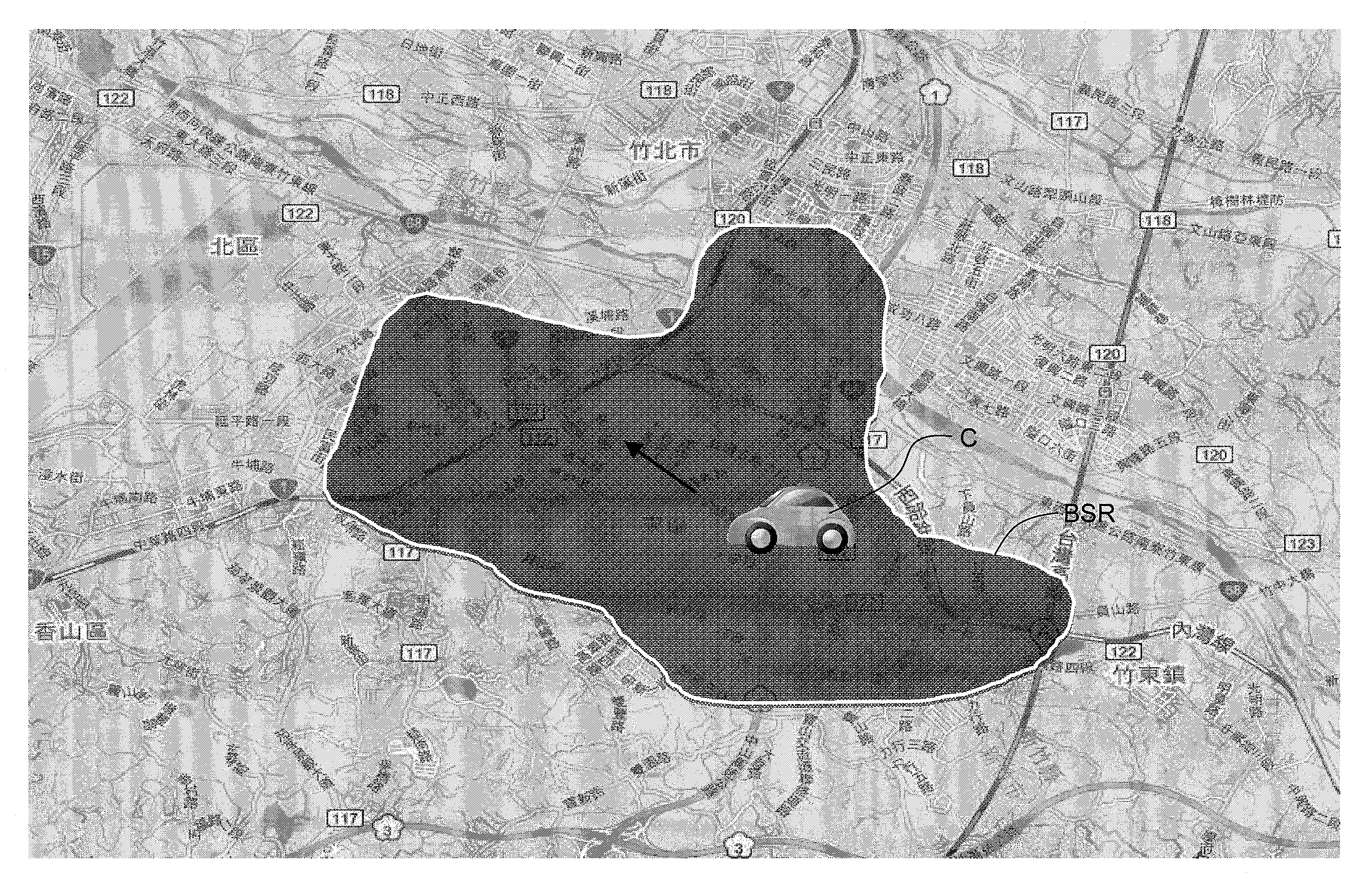

first exemplary embodiment

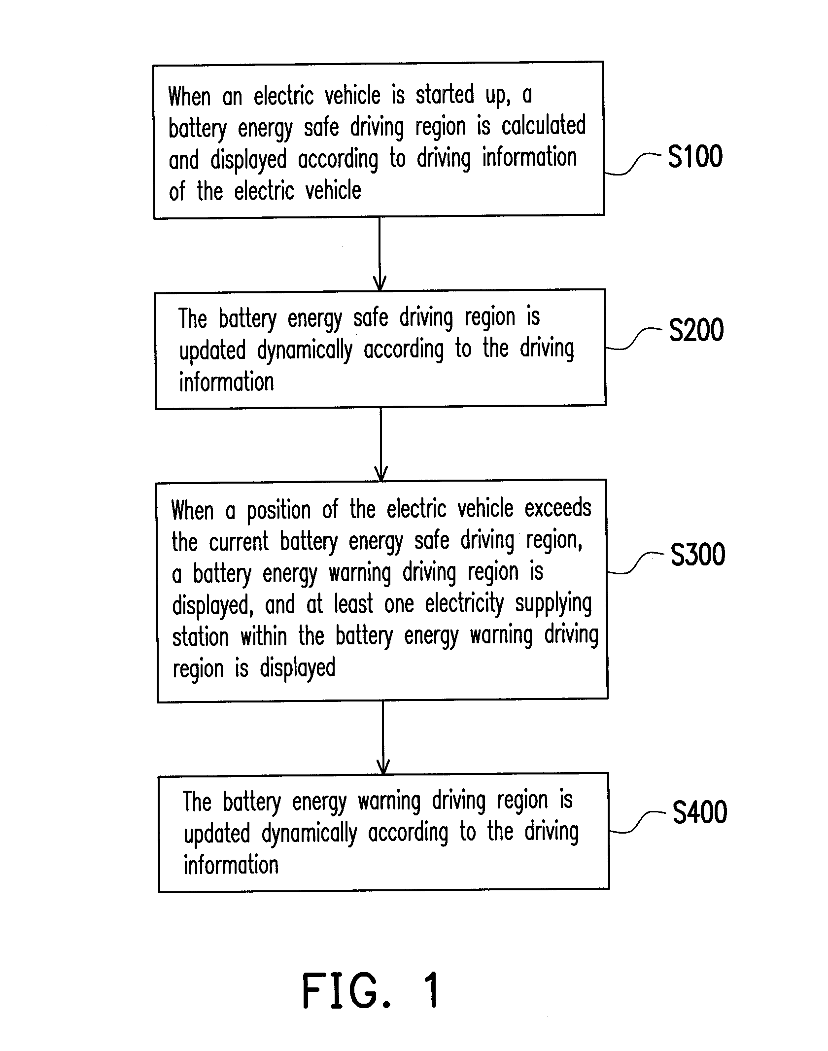
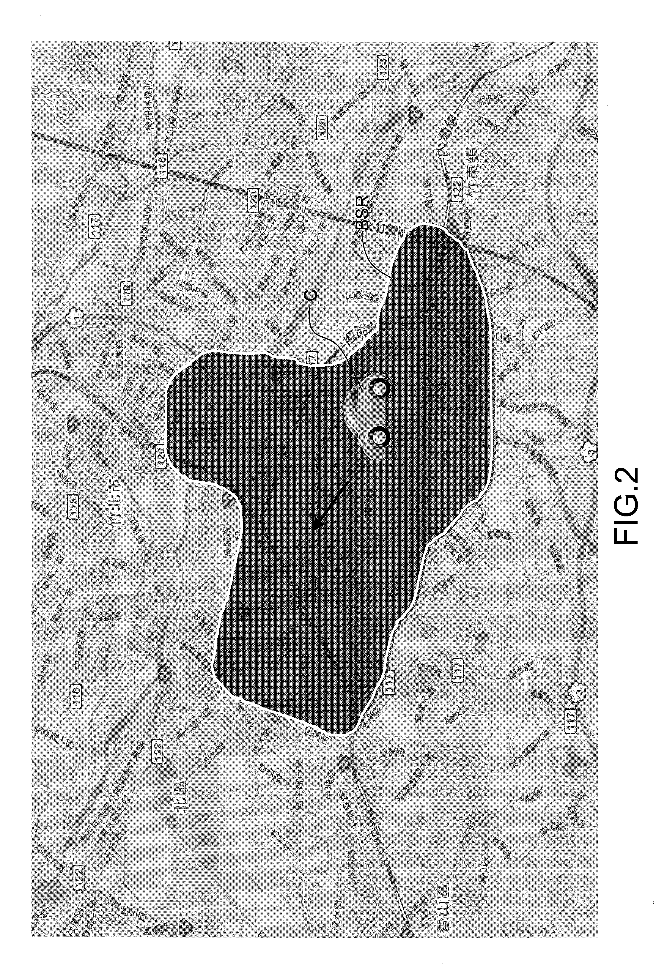
[0030]Referring to FIG. 1 and FIG. 2-FIG. 4, FIG. 1 is a flowchart illustrating a driving assistant method for an electric vehicle according to a first exemplary embodiment of the disclosure, and FIG. 2-FIG. 4 are operational schematic diagrams of a driving assistant method for an electric vehicle according to the first exemplary embodiment of the disclosure.

[0031]The driving assistant method for an electric vehicle of the disclosure includes following steps.

[0032]In step S100, as shown in FIG. 2, when an electric vehicle C is started up, a battery energy safe driving region BSR of the electric vehicle C is calculated and displayed according to driving information of the electric vehicle C, for example, battery information of the electric vehicle C (including at least one of electricity consumption status information, remained battery energy information and battery aging information of the electric vehicle C). Moreover, the driving information may include at least one of vehicle wei...

second exemplary embodiment

[0050]Referring to FIG. 12, FIG. 12 is a flowchart illustrating a driving assistant method for an electric vehicle according to a second exemplary embodiment of the disclosure.

[0051]In a step S510 of selecting the electricity supplying stations (the same to the step S110 of the first exemplary embodiment), a purpose thereof is to estimate a moving region of the electric vehicle C to obtain a position of at least one electricity supplying station capable of supplying electricity, and a selecting method thereof is as that described in the step S110 of the first exemplary embodiment, by which besides specified by the user, there are two operation modes of a directional mode and a non-directional mode. Therefore, before the step of selecting the electricity supplying station, a mode switching step S502 is added, and if the direction mode is switched, direction information can be further obtained (step S504), and the direction information is obtained through a global positioning system (...

third exemplary embodiment

[0084]Referring to FIG. 17, FIG. 17 is schematic diagram illustrating a driving assistant system for an electric vehicle according to a third exemplary embodiment of the disclosure. The driving assistance system is described with reference of the operational schematic diagrams of FIGS. 8A-8C and FIG. 9-FIG. 11.

[0085]The driving assistance system 600 of the electric vehicle includes a driving information collecting unit 610, an input unit 620, a selection region calculating unit 630, a coverage region calculating unit 640 and a display device 650.

[0086]The driving information collecting unit 610 may include a general on board diagnosis (OBD) system, which has an information collecting module for collecting at least the battery information of the electric vehicle and the electricity supplying station information, and the information can be collected according to a navigation map or geographic information captured through a DSRC or 3G method, and the real-time traffic information (traf...


PUM


Abstract

A driving assistant method for an electric vehicle is provided with the following steps. When the electric vehicle is started up, a battery energy safe driving region is calculated and displayed. The battery energy safe driving region is updated dynamically according to vehicle information. The vehicle information includes battery information of the electric vehicle.

Description

CROSS-REFERENCE TO RELATED APPLICATION[0001]This application claims the priority benefit of Taiwan application serial no. 100103461, filed Jan. 28, 2011. The entirety of the above-mentioned patent application is hereby incorporated by reference herein and made a part of this specification.BACKGROUND[0002]1. Field of the Disclosure[0003]The disclosure relates to a driving assistant method and system for an electric vehicle capable of dynamically displaying a guiding region.[0004]2. Description of Related Art[0005]Under global concern of green energy issues and environmental protection issues, low emission or zero emission electric vehicle industry becomes a focus of development in transportation equipments. Regardless of what kind of future electric vehicle may become a mainstream, from electric buses to electric cars all have a demand for electricity charging. Although it is most likely to build a large number of electricity supplying equipments (for example, charging equipment inst...

Claims


Application Information

Patent Timeline
IPC IPC(8): G08B21/00B60L9/00
CPCB60W40/12B60W50/0097B60W50/14B60W2510/244G01C21/3469B60W2520/10B60W2530/10B60W2550/143B60W2550/402B60W2510/248B60W2552/20B60W2556/50
Inventor TSAI, I-TALIN, YU-HUIWU, CHENG-YULIN, YI-CHUNCHANG, CHANNING
Owner IND TECH RES INST
Learn More