Electrical Brushless Motor

a brushless motor and electric technology, applied in the direction of motor/generator/converter stopper, electronic commutator, dynamo-electric converter control, etc., can solve the problems of difficult to design a motor that can be adapted to these various configurations with minimal changes, inability to free up the gain in efficiency, and the cost of brushless motors is more expensive than induction motors. , to achieve the effect of reducing the number of wires passing

Inactive Publication Date: 2012-08-02
ELECTRICAL SYST INTEGRATOR
View PDF2 Cites 29 Cited by
  • Summary
  • Abstract
  • Description
  • Claims
  • Application Information

AI Technical Summary

Benefits of technology

[0008]A feature of the present invention is to provide a new brushless motor design that can be used in various configurations and which minimizes the number of wires passing through the axis or shaft of the brushless motor device.
[0009]A further feature of the present invention is to provide a brushless motor device, which simplifies the overall wiring.
[0010]An additional feature of the present invention is to provide simplified interconnections between the motor and motor controller, as well as other components of the brushless motor device.

Problems solved by technology

To be able to design a motor that can be adapted to these various configurations with minimal changes is often difficult.
Use of brushless motors for a ceiling fan can meet the present day energy star requirements of efficiency; however gain in this efficiency is not free.
Brushless motors are more expensive than induction motors.
The electrical interconnections become more complicated than induction motors due to the electrical interconnections between the user interface and the control, and additional interconnection schemes are required for the motor and the motor controller.
The traditional construction of a brushless motor for the ceiling fan thus provides a lot of challenges in terms of electrical wire-up to achieve all the functionality of the ceiling fan with various user interfaces.
Properly routing these wires through the cross-drilled holes into the hollow shaft and again dressing them properly into the control board is both cumbersome and labor intensive.

Method used


Image

  • Electrical Brushless Motor
  • Electrical Brushless Motor
  • Electrical Brushless Motor

Examples


Embodiment Construction

[0039]The present invention relates to electrical brushless motors having unique and beneficial designs, and also relates to devices that utilize the electrical brushless motor, such as ceiling fans.

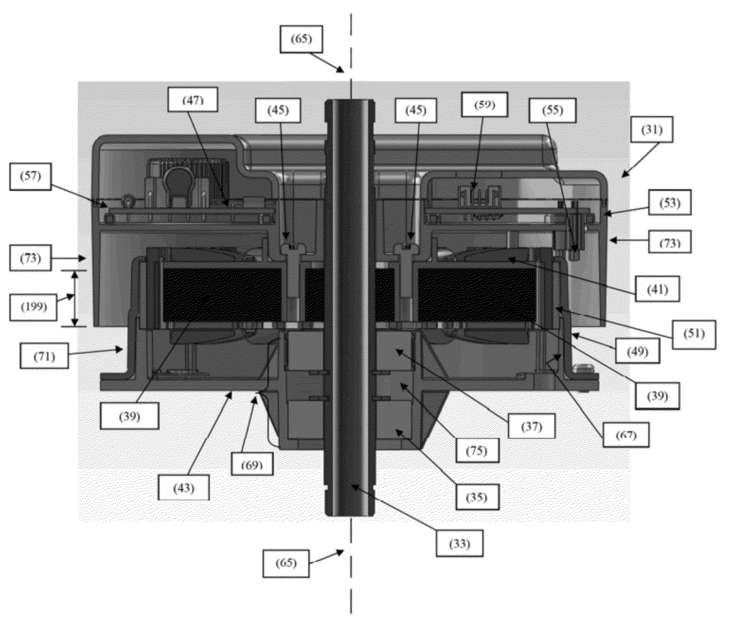
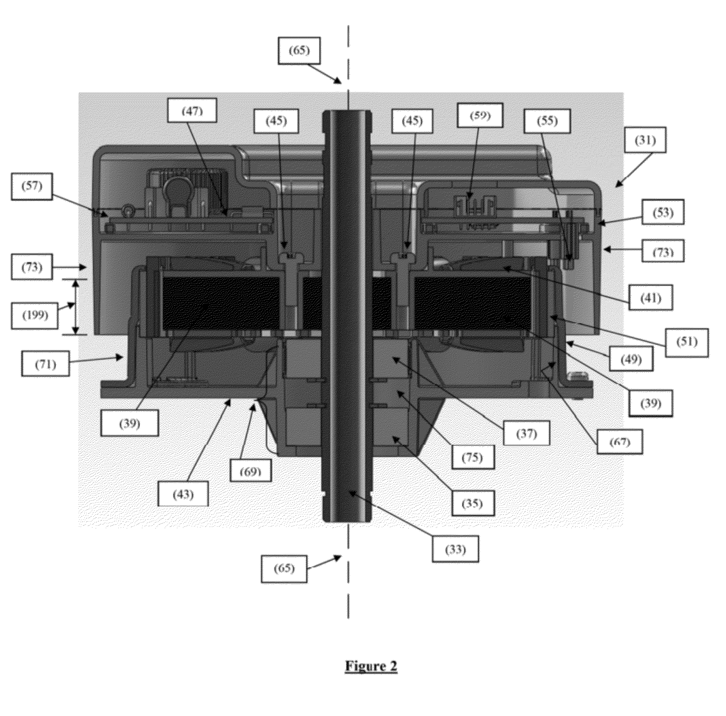
[0040]In more detail and with reference to the figures, wherein the figures are simply exemplary and non-limiting of the present invention, in FIG. 2, a brushless motor of the present invention is shown. In FIG. 2, an electrical brushless motor (31) includes a stator (39) having an axis (65). The axis is in line with the shaft (33), which can be a hollow or solid shaft (33). The electrical brushless motor (31) further includes multiple stator windings (41) or motor coils (41). A circular casing (49) with an inner periphery (67) has a permanent magnet(s) (51) present on the inner periphery (67) and interacting with the stator windings (41) of the stator (39). The electrical brushless motor (31) of the present invention further includes at least one row of bearings (also referred to as bea...


PUM


Abstract

An electrical brushless motor is described, as well as a ceiling fan utilizing the electrical brushless motor.

Description

[0001]This application claims the benefit under 35 U.S.C. §119(e) of prior U.S. Provisional Patent Application No. 61 / 436,648, filed Jan. 27, 2011, which is incorporated in its entirety by reference herein.BACKGROUND OF THE INVENTION[0002]The present invention relates to brushless motors and new configurations and designs. The present invention further relates to ceiling fans and other devices that contain the brushless motor(s) of the present invention.[0003]Traditional ceiling fans use induction motors as their prime movers. Ceiling fans as the name suggests are typically hung on the ceiling and have blades mounted on the periphery of the motor to generate airflow. Ceiling fans currently available in the market are capable of different speed settings, typically 3 or 4 distinct speeds. Typically they run in both clockwise and counter-clockwise direction to provide downdraft in the summer time and updraft in the winter time. In addition, most of the fans have a down or up light on t...

Claims


Application Information

Patent Timeline
IPC IPC(8): H02P6/18H02K5/22H02K29/08H02K7/08H02K11/00
CPCH02K7/14H02K29/08H02K21/22H02K11/0073H02K11/33
Inventor PUROHIT, MADHUR M.
Owner ELECTRICAL SYST INTEGRATOR
Why Eureka
Try Eureka