
Rail vision system

a vision system and rail technology, applied in the field of rail vision systems, can solve the problems of significant property damage and injury to passengers, crew and bystanders, and the impact of railroad components on the safety and reliability of the track and the rail, and achieve the effects of reducing the safety and reliability of the track and rail, reducing the safety of the track, and reducing the safety of the rail

Inactive Publication Date: 2012-08-02
HARSCO CORP
View PDF9 Cites 97 Cited by
  • Summary
  • Abstract
  • Description
  • Claims
  • Application Information

AI Technical Summary

Benefits of technology

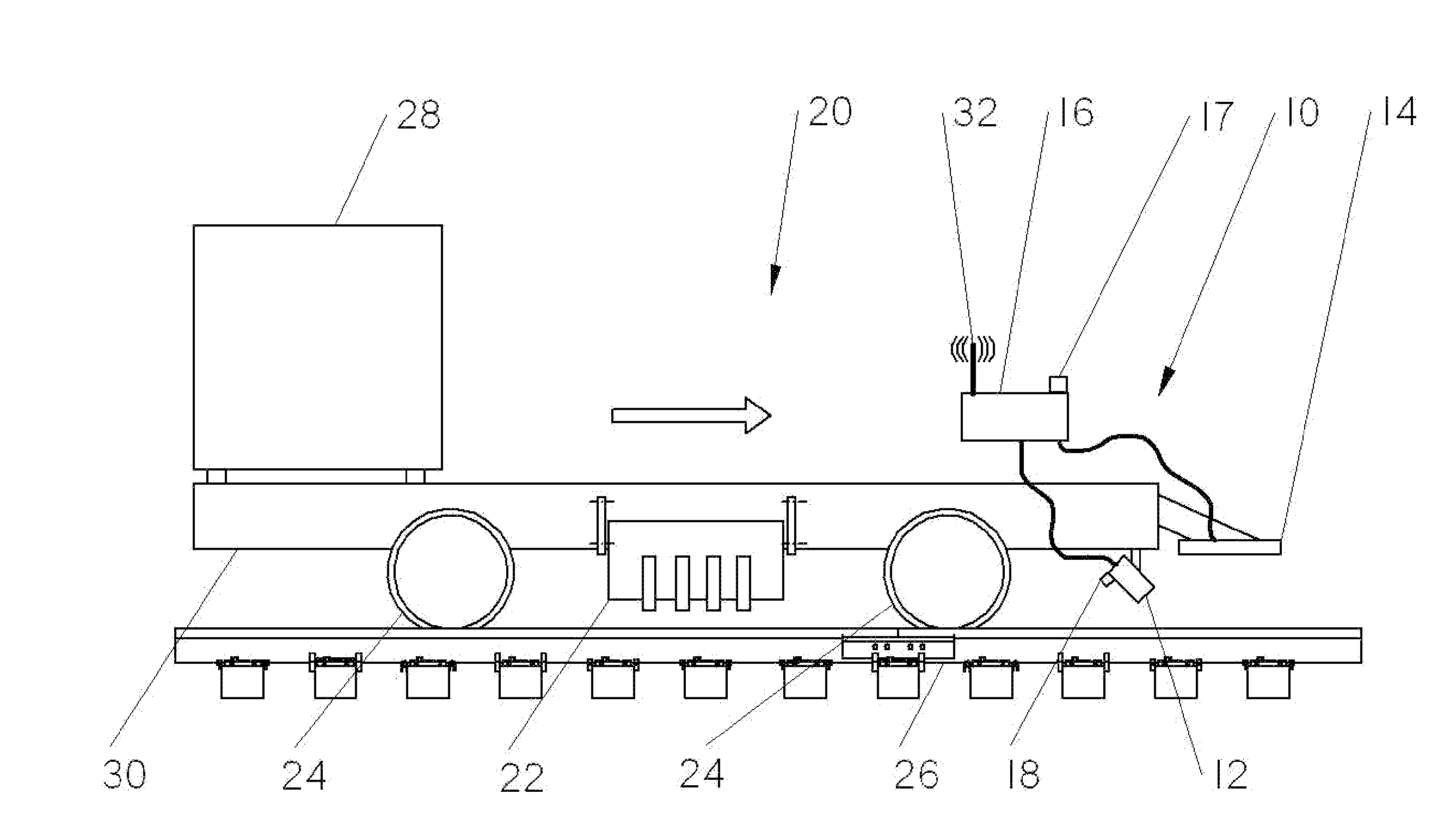
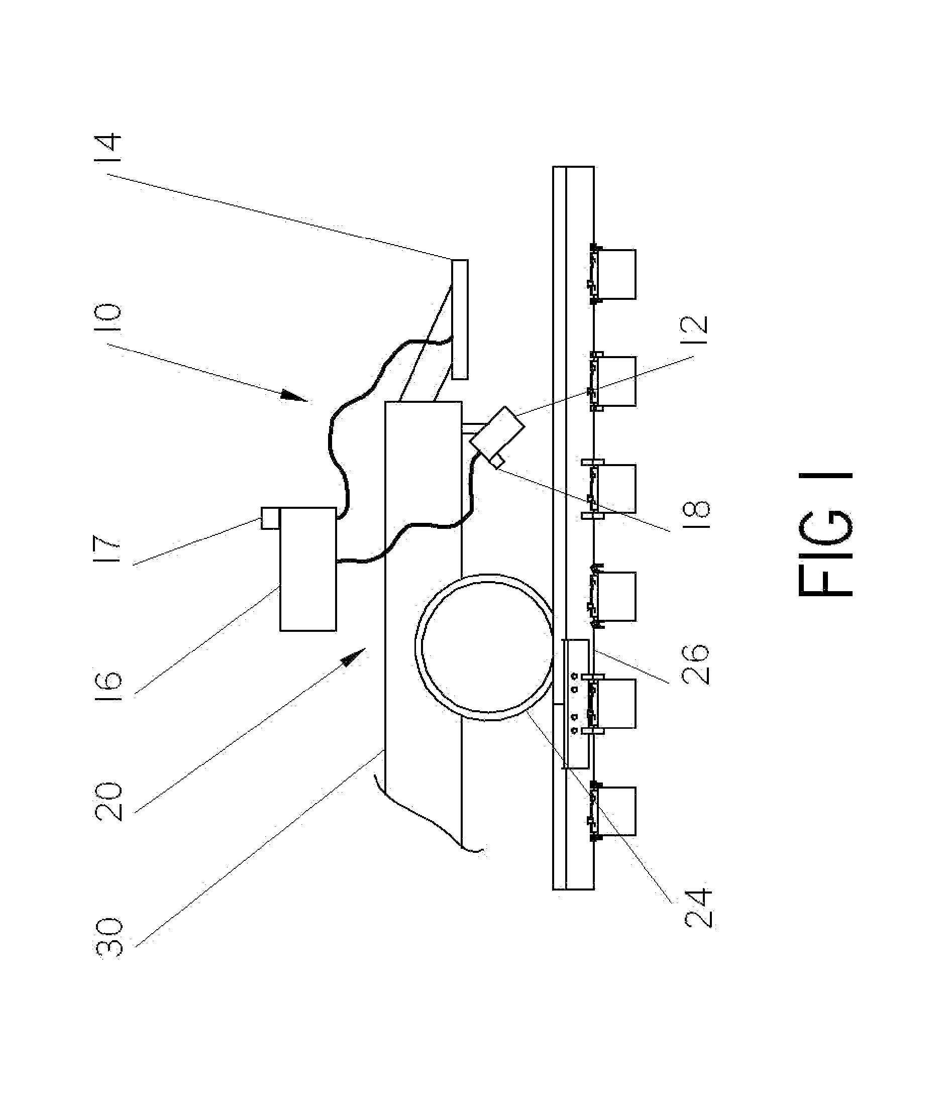
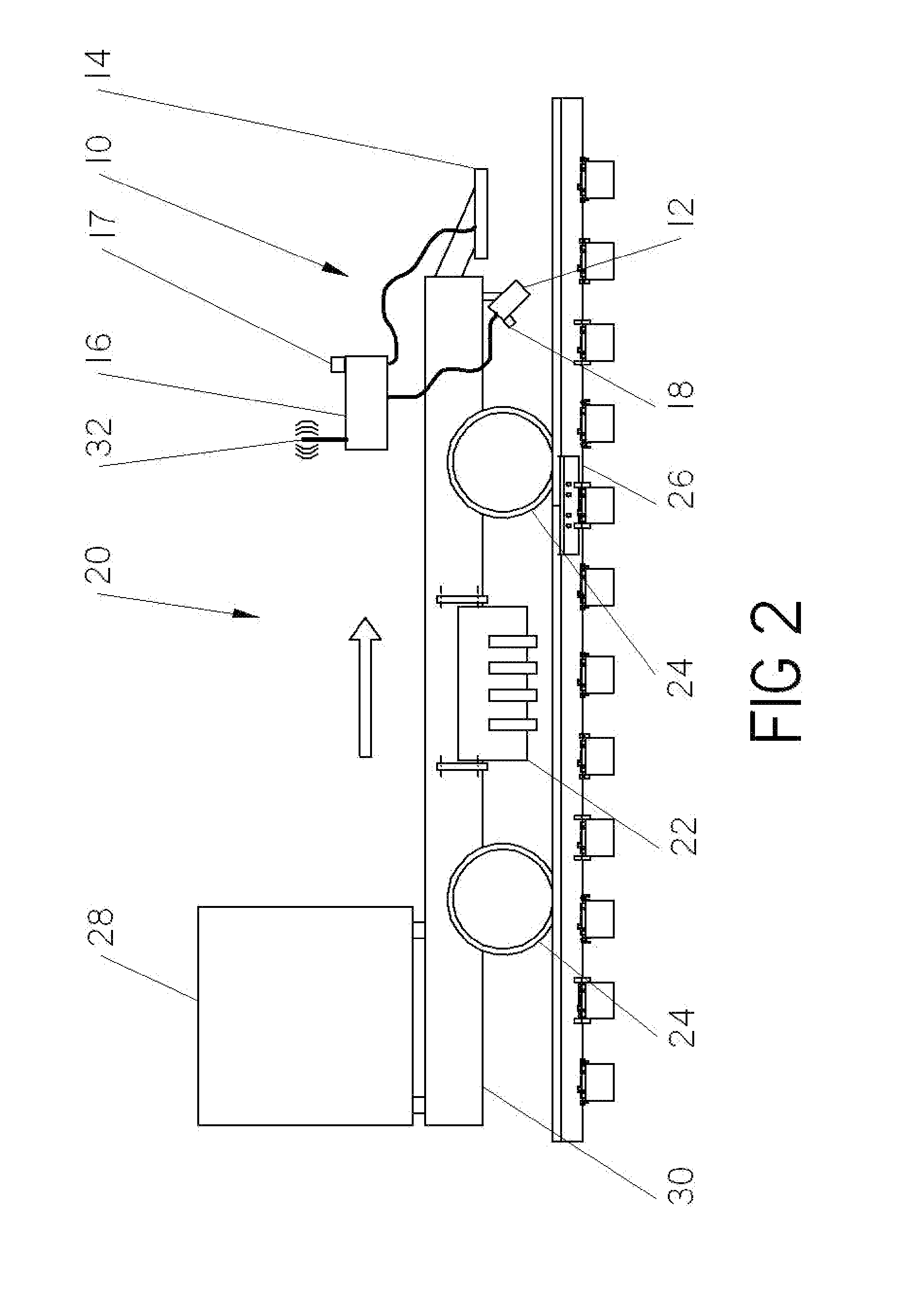
[0017]An exemplary embodiment is directed to a vision inspection system for use with a railcar or a vehicle adapted to travel on a railroad track and perform maintenance on rail components of the railroad track, the vision inspection has a vision device adapted to provide an image of each rail component. An image recognition component analyzes the images taken by the vision device to determine the type and condition of each rail component as the vehicle is traveling on the railroad track. A control system communicates with the vision device and the image recognition component. The control system causes workheads of the vehicle to engage respective rail components based on the input received from the vision inspection system.

Problems solved by technology

The condition of the railroad components greatly impacts safety and reliability of the track and the rail transportation.
Failure or degradation of various rail components of a railroad track can cause derailment of a train traveling on the track.
Such derailment can cause significant property damage and injury to passengers, crew and bystanders.
However, the quality of visual inspection is generally poor, especially when the visual inspection is performed from a hi-rail vehicle, which is a vehicle that has been modified to drive on railroad tracks.
The limitation of this prior art method of inspecting railroad components is that it is time-consuming and labor intensive, particularly as the operator must then position various machines of the rail consist over the problem areas.
However, inspection performed on foot is a slow and tedious process, requiring many hours to inspect several miles of railroad track.
The significant limitation of the inspection vehicle disclosed in Trosino et al. and the method taught therein requires the inspector to continually perform visual inspection of the railroad track while traveling on the railroad track, such inspection being not much better in quality than the conventional inspection method from a hi-rail vehicle noted above.
Therefore, whereas the railcar vehicle of Trosino et al. is appropriate for inspecting a railroad track for large anomalies which are easily visible to the inspector, such as the presence of weeds, blocked drain, etc., the described inspection vehicle does not allow facilitated inspection of smaller rail components or smaller defects associated therewith.
Other systems, such as the VISTA system, a product of Loram, Inc., are of more limited application, primarily on rail grinders.
While these systems all generate digitized rail head profiles for the running rails, they do not analyze or generate digitized profiles for spikes, tie plates, anchors or other such components.
The usefulness of such prior systems has been limited to running rails.
In addition, while these systems generate a digital profile of the rail head, the cameras are not located on the actual equipment which performs the maintenance.

Method used


Image

  • Rail vision system
  • Rail vision system
  • Rail vision system

Examples


Embodiment Construction

[0028]FIG. 1 shows an illustration of a vision system 10 in accordance with one example embodiment of the present invention that facilitates identification, location and / or inspection of rail components while traveling on the railroad track. Components may include, but are not limited to, ties, tie plates, anchors and spikes.

[0029]As will be discussed below, the vision system 10 utilizes digital images or pictures, computer imaging, and illumination technologies to allow accurate and efficient location and inspection of rail components, with reduced time and effort as compared to conventional methods. It should be initially noted that whereas the present invention is described in detail below as locating spikes, tie plates and anchors, the present invention is not limited thereto, and may be utilized for location and / or inspection of any rail component that can appropriately be inspected using the vision system 10.

[0030]As shown in FIG. 1, the vision system 10 of the illustrated emb...


PUM


Abstract

A vision inspection system and method for use with a railcar includes a vision device adapted to provide an image of each rail component. An image recognition component analyzes the images taken by the vision device to determine the type and condition of each rail component as the vehicle is traveling on the railroad track. A control system communicates with the vision device and the image recognition component. The control system causes workheads of the vehicle to engage respective rail components based on the input received from the vision inspection system. A method for determining the relative distance between the rail components includes comparing the position of the respective rail components of a first image to the position of the respective rail components of a second image to determine the distance between the respective components and distance the railcar has moved.

Description

FIELD OF THE INVENTION[0001]The present invention is directed to a system and method for locating rail components of a railroad track, and communicating such information to a satellite device.BACKGROUND OF THE INVENTION[0002]Maintaining proper condition of rail components of a railroad track is of paramount importance in the railroad transportation industry. Rail components include anchors, tie plates, spikes, ties, joint bars, etc. The condition of the railroad components greatly impacts safety and reliability of the track and the rail transportation. Failure or degradation of various rail components of a railroad track can cause derailment of a train traveling on the track. Such derailment can cause significant property damage and injury to passengers, crew and bystanders.[0003]Visual inspection by an operator is one way to monitor the condition of railroad track and components and to ensure that the track is in good condition. However, the quality of visual inspection is generall...

Claims


Application Information

Patent Timeline
Patent Type & Authority Applications(United States)
IPC IPC(8): E01B29/00G06K9/00G06F19/00
CPCB61K9/08B61L23/048B61L23/047B61L23/045
Inventor MILLER, ROBERT S.DELUCIA, ANTHONY P.
Owner HARSCO CORP
Learn More