
Tattoo needle stabilization device and method of use

a technology of a stabilizing device and a tattoo needle, which is applied in the field of tattoo needle stabilization devices, can solve the problems of robbery of the efficiency of the tattoo machine, not providing significant needle stabilization, etc., and achieves the effect of avoiding excessive wear

Inactive Publication Date: 2012-08-02
KLEBS DAVID +1
View PDF2 Cites 19 Cited by
  • Summary
  • Abstract
  • Description
  • Claims
  • Application Information

AI Technical Summary

Benefits of technology

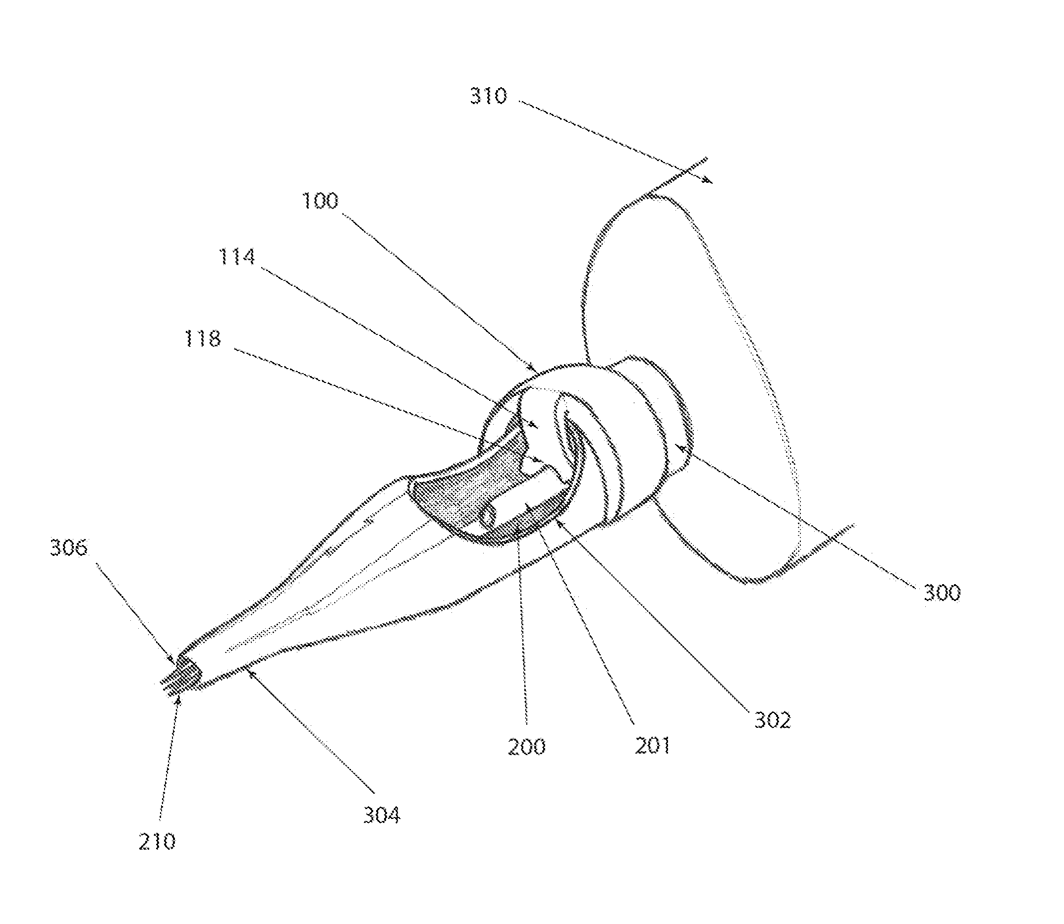
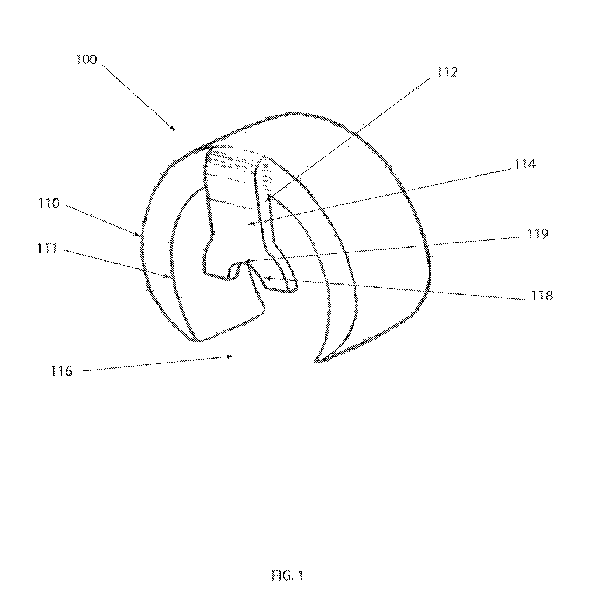
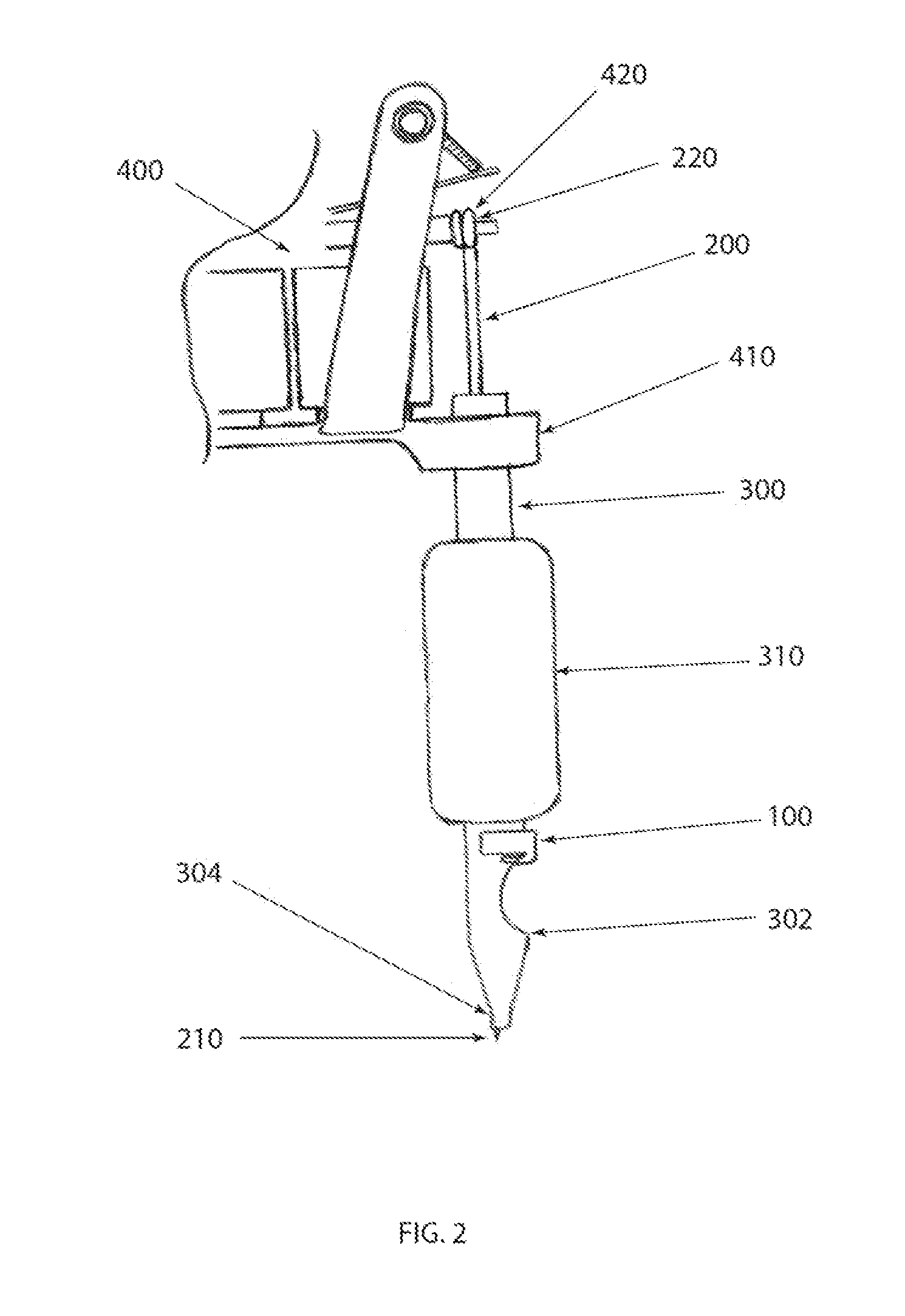
[0009]A first embodiment of the present invention is a needle stabilization device having, a clip portion that attaches over the outside of the sanitary tube, a support shaft that extends into the sanitary cut-out and a needle cradle that engages the shaft of the tattoo needle. The device is composed of a resilient material allowing it to substantially maintain its original shape after deformation, and to avoid excessive wear due to the tattoo needle oscillations. The clip is a circular ring having a portion removed to allow the clip to expand and snap over the outside surface of the sanitary tube, just above the sanitary cut-out. The shaft support member of the device extends away from the clip, perpendicular to the length of the sanitary tube, and is placed into the sanitary cut-out. The support cradle is placed over the shaft of the tattoo needle. When the tattoo needle stabilization device of the present invention is fully engaged with the outside of the sanitary tube, the apex of the cradle is positioned just beyond the centerline of the sanitary tube, causing a slight bend in the tattoo needle shaft. This configuration biases the point of the tattoo needle against the bottom of the tip aperture or guide. The pressure created is sufficient to allow an artist to accurately draw in any direction, including the traditional pushing motion, pulling back, on an arc, diagonal or side to side. It is contemplated that the stabilization device material is any one of plastic, nylon, polycarbonate, stainless steel, aluminum, titanium or another acceptable material. The device may be injection molded, cast or machined. Material considerations may include but are not limited to, resiliency to ensure a secure fit around the outside of the sanitary tube, wear due to needle oscillations, fatigue due to multiple uses, anti-microbial, sterilization, staining, cost and manufacturing constraints.
[0014]In one embodiment of the present invention, the needle stabilization device is a clip designed to engage the outside surface of the sanitary tube and having a grooved roller which engages the tattoo needle shaft through the sanitary cut-out. In yet another embodiment of the present invention, the needle stabilization device includes a roller that engages the shaft of the needle. The sanitary tube having a retaining groove for the stabilization device clip and a slot just above the sanitary cut-out for the roller to extend through. The roller configuration allows for improved needle oscillation and electrical efficiency.
[0015]In one embodiment of the present invention, the needle stabilization device is clip designed to be inserted through the sanitary cut-out and is attached to the uppermost edge of the cut-out, engaging both the inside and outside surfaces of the sanitary tube. The clip having a support member extending perpendicular from the clip and into the sanitary cut-out. The end of the support member includes a needle cradle which biases the tattoo needle point against the sanitary tube tip. In another embodiment, the clip is configured to engage the sides of the sanitary cut-out, preventing the clip from moving or rotating away from the uppermost edge of the cut-out.

Problems solved by technology

One issue with traditional tattoo machines is that the only solid attachment point for the needle is at the eye end, 5½ inches away from needle point, which is only loosely constrained in an aperture or guide.
This method does not provide significant needle stabilization and the rubber band also robs the efficiency of the tattoo machine.

Method used


Image

  • Tattoo needle stabilization device and method of use
  • Tattoo needle stabilization device and method of use
  • Tattoo needle stabilization device and method of use

Examples


Embodiment Construction

[0031]For the purposes of promoting an understanding of the principles in accordance with the disclosure, reference will be made to the embodiments illustrated in the drawings and specific language will be used to describe the same. It will nevertheless be understood that no limitation of the scope of the disclosure is thereby intended. Any alterations and further modifications of the inventive features illustrated herein, and any additional applications of the principles of the disclosure as illustrated herein, which would normally occur to one skilled in the relevant art and having possession of this disclosure, are to be considered within the scope of the disclosure.

[0032]As used in this specification and the appended claims, the singular forms “a,”“an,” and “the” include plural referents unless the context clearly dictates otherwise. In describing and claiming the present disclosure, the following terminology will be used in accordance with definitions set out below. As used her...


PUM

PropertyMeasurementUnit
Diameteraaaaaaaaaa
Flexibilityaaaaaaaaaa
Elasticityaaaaaaaaaa

Abstract

The present invention relates generally to a tattoo needle stabilization device. More specifically, this disclosure relates to a device that is inserted through the sanitary cutout and engages the shaft of a tattoo needle near the point, biasing the point of the needle against the inside of the tip aperture and stabilizing the needle.

Description

[0001]The following application claims priority to provisional application 61 / 437,631 filed Jan. 29, 2011.BACKGROUND OF THE INVENTION[0002]The present invention relates generally to a tattoo needle stabilization device. More specifically, this disclosure relates to a device that engages the shaft of a tattoo needle near the point, biasing the point of the needle against the inside of the tip aperture and stabilizing the needle.[0003]Tattooing is the process of placing indelible ink under the surface of the skin, creating permanent marks and ornamentation. The true origin of tattooing is largely unknown but, it is an art form that crosses cultures and continents. The earliest tattoos date back over 5000 years and can be identified in great civilizations such as the Greeks, Romans and Egyptians. More recent tattoo cultures include, the Polynesians, Celts and Japanese. Past tattoos were applied by hand, where an artist would dip a sharp instrument or needle into ink and painstakingly p...

Claims


Application Information

Patent Timeline
IPC IPC(8): A61M37/00B23P11/00
CPCY10T29/49401A61M37/0076
Inventor KLEBS, DAVIDCASTLE, JONATHAN
Owner KLEBS DAVID
Learn More