
Computer System and Operating System Switching Method Thereof

a computer system and operating system technology, applied in the field of computer systems, can solve the problems of user not knowing that the operating system behind is still operating, more power consumption, and takes a long time to switch between operating systems

Active Publication Date: 2012-07-26
VIA TECH INC
View PDF12 Cites 33 Cited by
  • Summary
  • Abstract
  • Description
  • Claims
  • Application Information

AI Technical Summary

Benefits of technology

[0008]An operating system switching method is provided. The operating system switching method is for a computer system comprising a control unit, a memory unit, and a storage unit, wherein the storage unit comprises a first operating system and a second operating system. The steps of the method include: loading the first operating system and the second operating system into a first memory space and a second memory space of the memory unit, respectively, and setting the first memory space and the second memory space to a working state and a standby state, respectively; and performing a first switching of the operating systems, and setting the first memory space and the second memory space to the standby state and the working state, respectively.
[0009]A computer system is further p

Problems solved by technology

However, the rebooting process requires the whole computer system to be in a shutdown state (e.g. S5) from the working state (e.g. S0), and then re-enter the working state (e.g. S0), such that it takes a very long time to switch between operating systems.
A user does not know the operating system behind is still operating with proper design.
Also, more power is consumed as two operating systems must be executed by a processor; especially for devices which have slower processors, like mobile devices.

Method used


Image

  • Computer System and Operating System Switching Method Thereof
  • Computer System and Operating System Switching Method Thereof
  • Computer System and Operating System Switching Method Thereof

Examples


Embodiment Construction

[0015]The following description is of the contemplated mode of carrying out the invention. This description is made for the purpose of illustrating the general principles of the invention and should not be taken in a limiting sense. The scope of the invention is determined by reference to the appended claims.

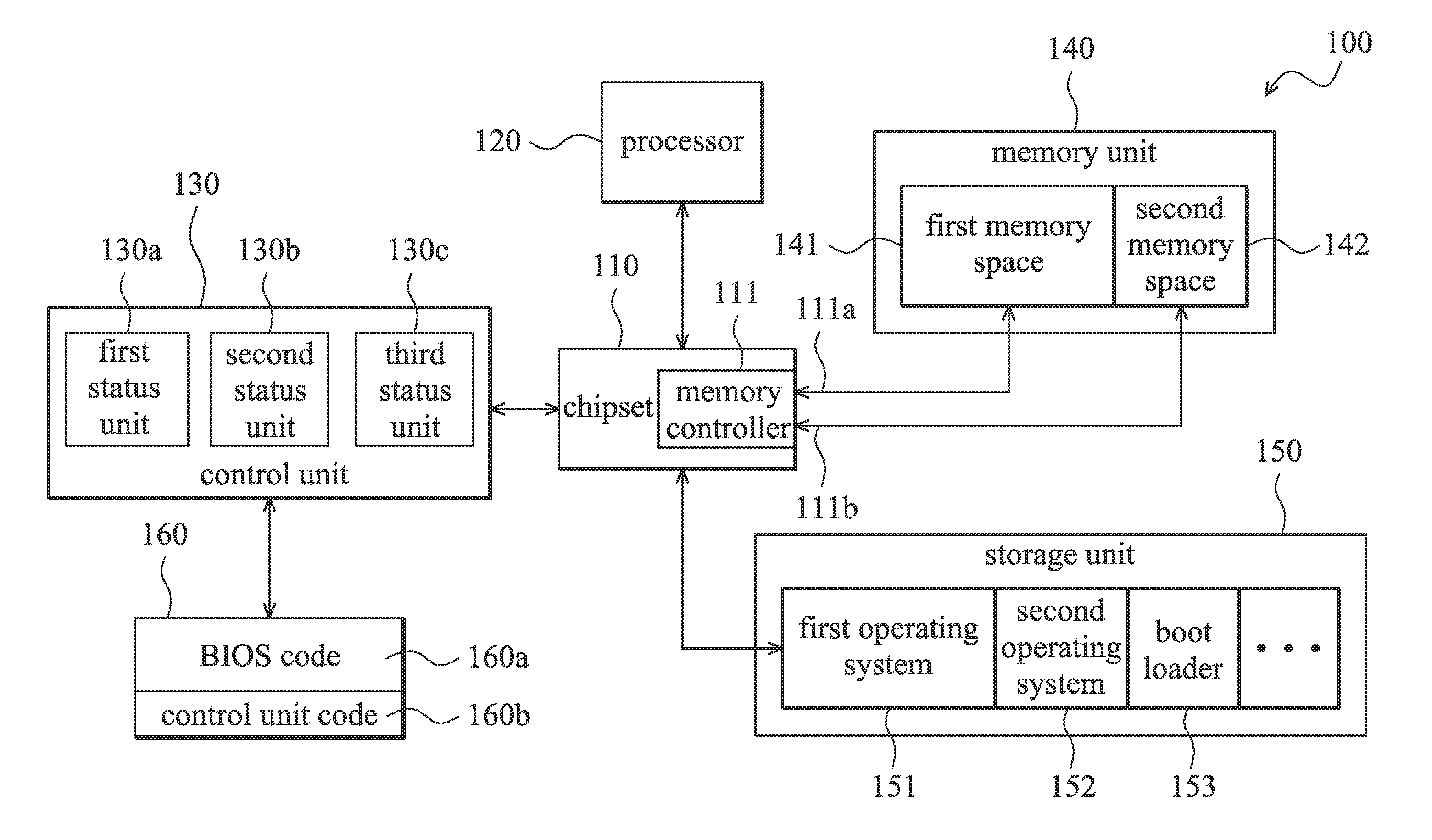
[0016]FIG. 1 illustrates a block diagram of the computer system 100 with multiple operating systems according to an embodiment of the invention. The computer system 100 at least comprises a chipset 110, a processor 120, a control unit 130, a memory unit 140, and a storage unit 150. In one embodiment, the computer system 100 can be a personal computer, a hand-held device, or a smart phone. In another embodiment, the computer system 100 further comprises a read-only memory 160, which is electrically coupled to the control unit 130. The read-only memory 160 further comprises a basic input / output system (BIOS hereafter) code 160a and a control unit code 160b. The BIOS code 160a cont...


PUM


Abstract

An operating system switching method is provided. The operating system switching method is for a computer system comprising a control unit, a memory unit, and a storage unit, wherein the storage unit comprises a first operating system and a second operating system. The steps of the method include: loading the first operating system and the second operating system into a first memory space and a second memory space of the memory unit, respectively, and setting the first memory space and the second memory space to a working state and a standby state, respectively; and performing a first switching of the operating systems, and setting the first memory space and the second memory space to the standby state and the working state.

Description

CROSS REFERENCE TO RELATED APPLICATIONS[0001]This Application claims priority of Taiwan Patent Application No. 100102799, filed on Jan. 26, 2011, the entirety of which is incorporated by reference herein.BACKGROUND OF THE INVENTION[0002]1. Field of the Invention[0003]The present invention relates to computer systems, and in particular relates to computer systems with multiple operating systems, which allows rapid switching between operating systems, thus consuming less power.[0004]2. Description of the Related Art[0005]For conventional computer systems (e.g. computer systems with Microsoft Windows operating system), power management for reducing power consumption can be achieved by using the standby states defined by the “Advanced Configuration and Power Interface (ACPI)”. There are six states S0 to S5 defined by the ACPI. State S0 indicates that the computer system is at working state. In the standby state 51, the CPU in the computer system is not working, and in the standby state ...

Claims


Application Information

Patent Timeline
IPC IPC(8): G06F12/06G06F9/06
CPCG06F1/3275G06F1/329Y02B60/1228G06F9/4893Y02B60/144G06F9/461Y02D10/00
Inventor WU, CHIN-HWAUNHUANG, CHUNG-CHINGCHANG, KUO-HANLIN, TAI-YU
Owner VIA TECH INC
Learn More