Depth Probe for the Humeral Head

a probe and humeral head technology, applied in the field of depth probes for the humeral head, can solve problems such as screw length and process errors

Inactive Publication Date: 2012-07-26
DEPUY SYNTHES PROD INC
View PDF9 Cites 15 Cited by
  • Summary
  • Abstract
  • Description
  • Claims
  • Application Information

AI Technical Summary

Problems solved by technology

Determining a length of bone screw that should be used for fixing the plate to the humeral head, however, is a difficult process since the far cortex of the humeral head is often thin and weak.
The depth gauge in this process, however, is not guided so that the measured depth may be inaccurate, resulting in the use of an incorrect screw length.

Method used


Image

  • Depth Probe for the Humeral Head
  • Depth Probe for the Humeral Head
  • Depth Probe for the Humeral Head

Examples


Embodiment Construction

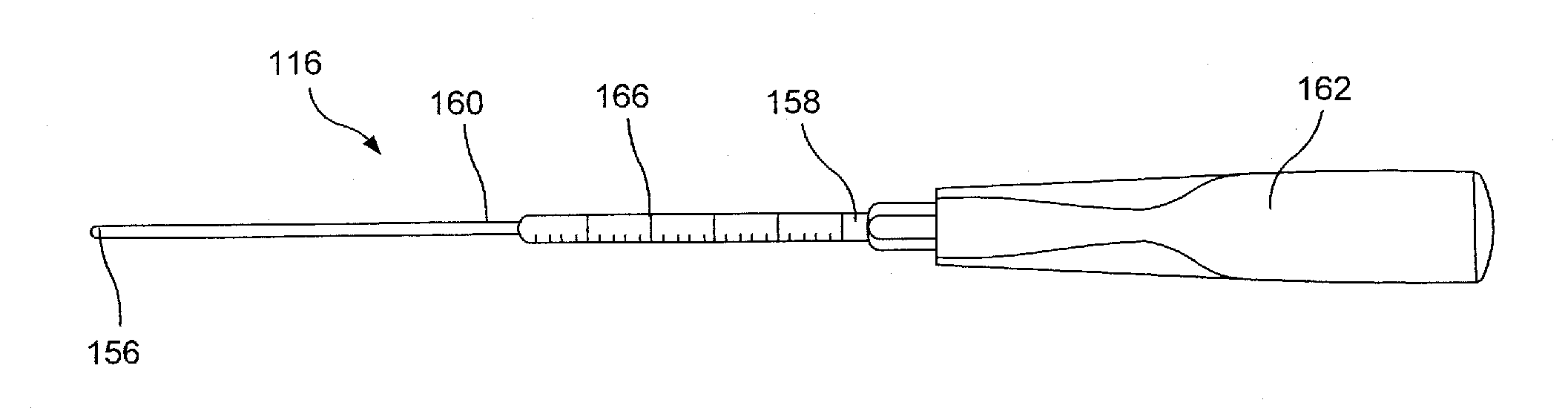
[0019]The present invention may be further understood with reference to the following description and the appended drawings, wherein like elements are referred to with the same reference numerals. The present invention relates to the treatment of bone fractures and, in particular, relates to a system and method for determining a length of a bone fixation element to be inserted into a head portion of a bone. Exemplary embodiments of the present invention describe a method of inserting a depth probe into the humeral head in a guided fashion to measure a length of screw that should be inserted therein. Although the exemplary embodiments specifically describe measuring a depth of a humeral head, it will be understood by those of skill in the art that the system and method of the present invention may be used to measure the depth of a head portion of any long bone.

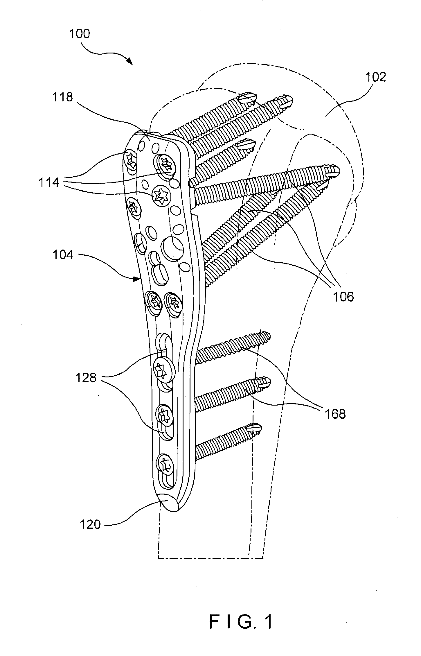
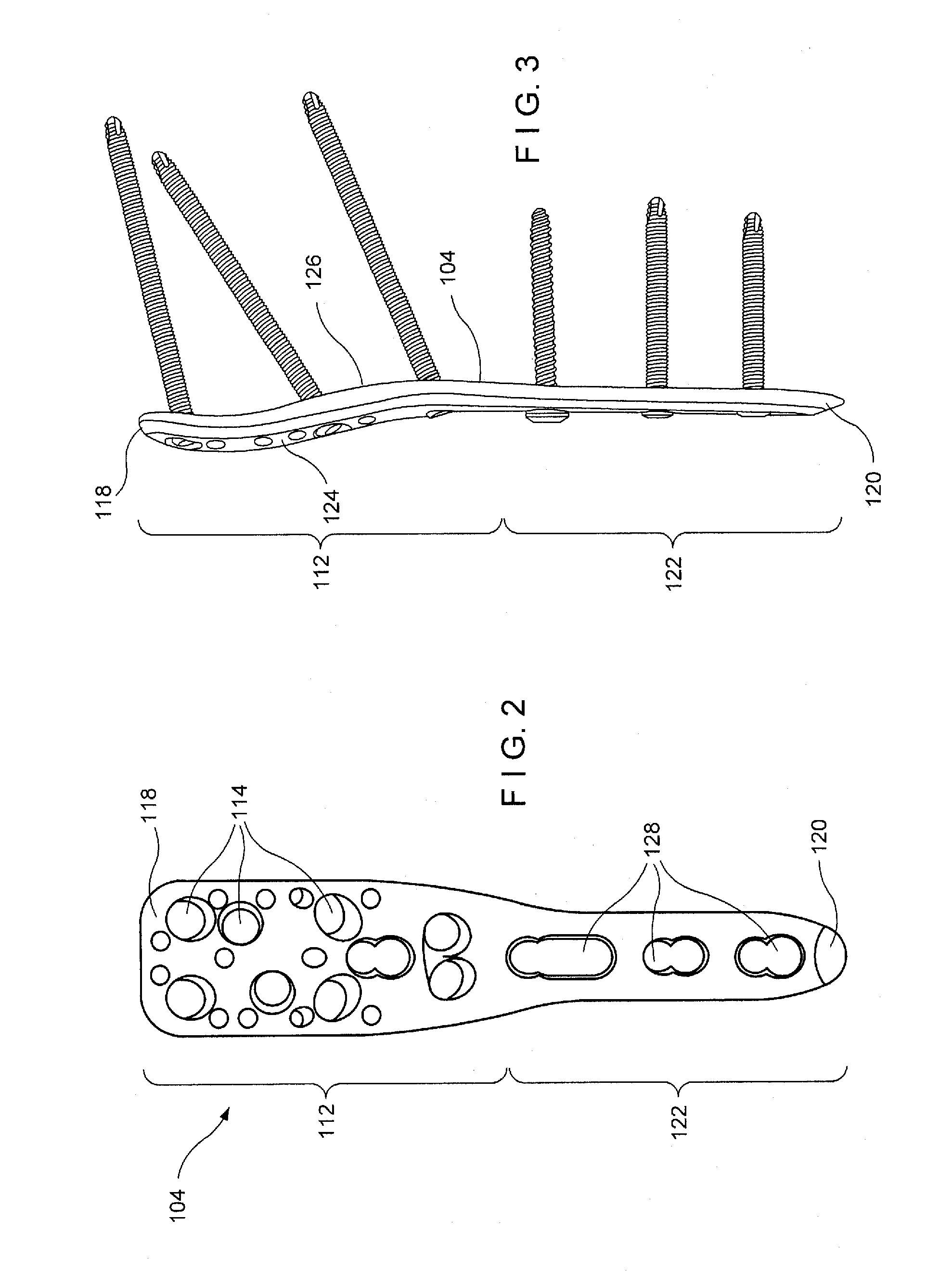
[0020]As shown in FIGS. 1-6, a system 100 for fixing a fracture according to an exemplary embodiment comprises a bone plate 1...


PUM


Abstract

A method for treating fractures comprises positioning a bone fixation device along a bone and creating a first hole from an outer surface of the bone through a lateral cortex to a central portion thereof, the first hole corresponding to a position at which a first bone fixation element receiving opening is to be located when the bone fixation device is coupled to the bone in a desired orientation in combination with inserting and pushing a probe through the central portion of the bone until a tip of the probe contacts an interior structure of the bone providing resistance to penetration by the probe increased relative to the central portion of the bone and determining a first length of the portion of the probe extending into the bone via the first hole to select a desired length of a first bone fixation element to be inserted therethrough.

Description

BACKGROUND [0001]Proximal humeral fractures are common in osteoporotic bone and may be fixed using a bone plate and a plurality of bone screws. For optimal fixation, the screw tip should be in close proximity to the far cortex. Determining a length of bone screw that should be used for fixing the plate to the humeral head, however, is a difficult process since the far cortex of the humeral head is often thin and weak. Currently, the length of screw is determined by pre-drilling a hole into the humeral head and inserting a standard depth gauge therein to measure a depth of the pre-drilled hole. The depth gauge in this process, however, is not guided so that the measured depth may be inaccurate, resulting in the use of an incorrect screw length. Studies have shown that the rate of screw tips penetrating into the joint is as high as 14%.SUMMARY OF THE INVENTION[0002]The present invention is directed to a method for treating a fractures comprising positioning a bone fixation device alon...

Claims


Application Information

Patent Timeline
Patent Type & Authority Applications(United States)
IPC IPC(8): A61B17/56
CPCA61B17/1725A61B17/1739A61B2019/462A61B2017/1778A61B17/8061A61B2090/062A61B17/1778
Inventor JOST, RETOTHOMAS, GAVIN
Owner DEPUY SYNTHES PROD INC
Why Eureka
Try Eureka