Closed drift ion source with symmetric magnetic field

Inactive Publication Date: 2012-07-26
MADOCKS JOHN E
View PDF7 Cites 24 Cited by
  • Summary
  • Abstract
  • Description
  • Claims
  • Application Information

AI Technical Summary

Benefits of technology

[0008]The first and second magnetic paths can produce equal strength magnetic fields at the pole terminal surfaces on either side of the separation. The first and second magnetic paths are able to be constructed to have equal magnetic reluctances.
[0011]A process for providing a plasma is provided that includes providing a closed drift ion source. An ionizable gas is introduced into said closed drift ion source. A closed drift electron confining region is provided in a separation between a first pole terminal surface of a first pole and a second pole terminal surface of a second pole. A source of magnetic flux of a single magnetic field source is disposed in proximity between one of the first pole or the second pole such that the length of a first magnetic path between a first magnetic pole of said magnetic field source and the first pole terminal surface of said first pole is different from the length of a second magnetic path between the opposing magnetic pole to the first magnetic pole and the second pole terminal surface of the second pole. A first magnetic path and a second magnetic path are formed such that the closed drift electron confining region is symmetric in the separation. The introduction of gas predominately into closed drift electron confining region achieves particularly good operational performance.

Problems solved by technology

The presence of both center and outer magnets increases the complexity and cost of the ion sources, as compared to a single magnet ion sources.

Method used


Image

  • Closed drift ion source with symmetric magnetic field
  • Closed drift ion source with symmetric magnetic field
  • Closed drift ion source with symmetric magnetic field

Examples


Embodiment Construction

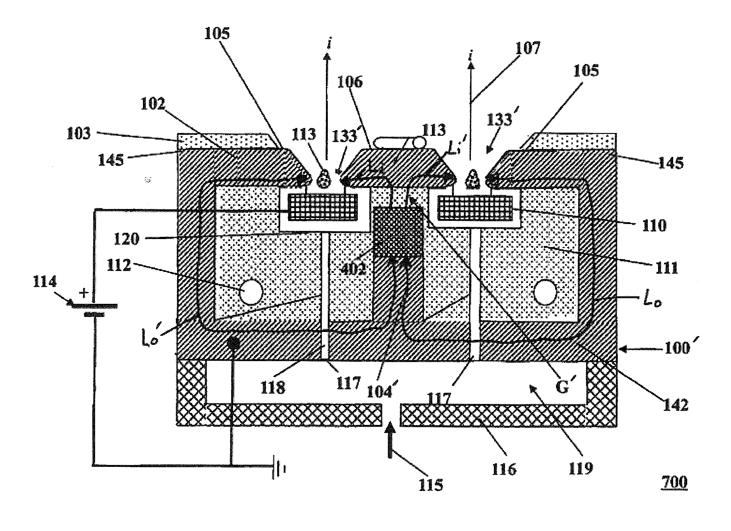
[0019]The present invention has utility as an ion source for substrate treatment or space craft propulsion. A simplified apparatus generating symmetric and stable ion beams is provided.

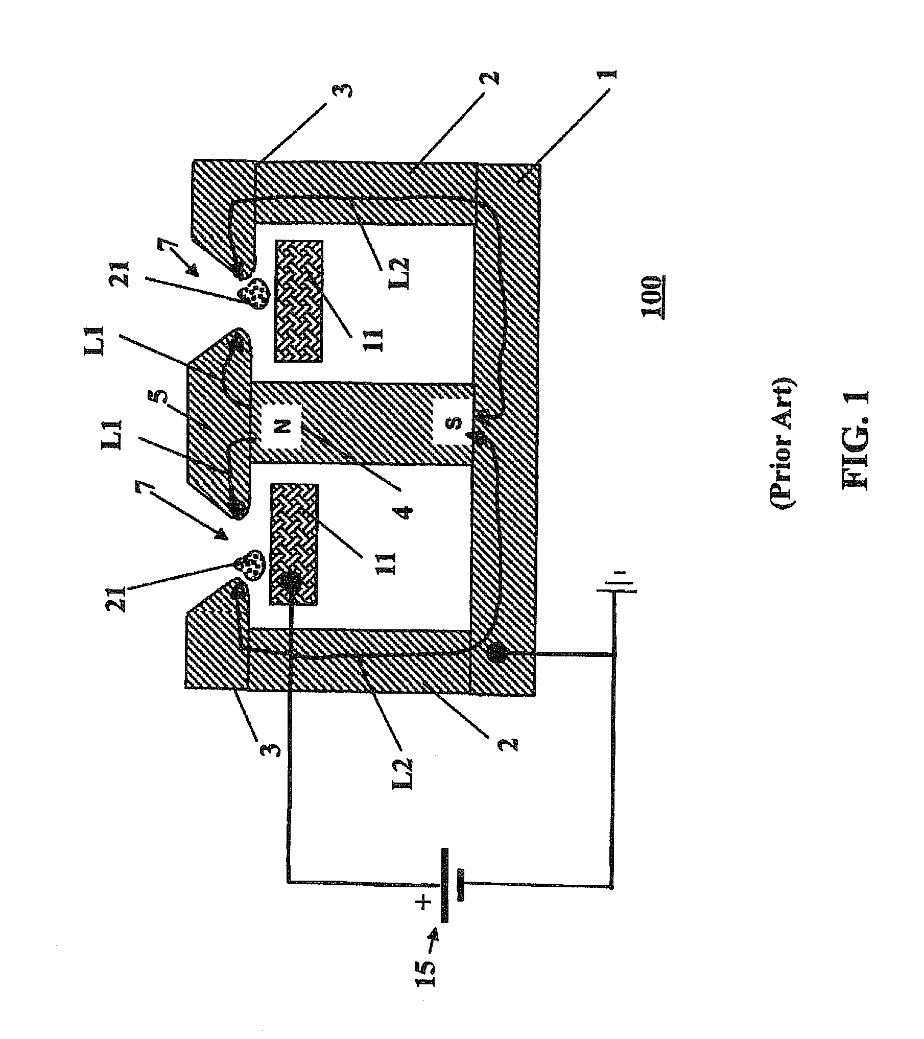
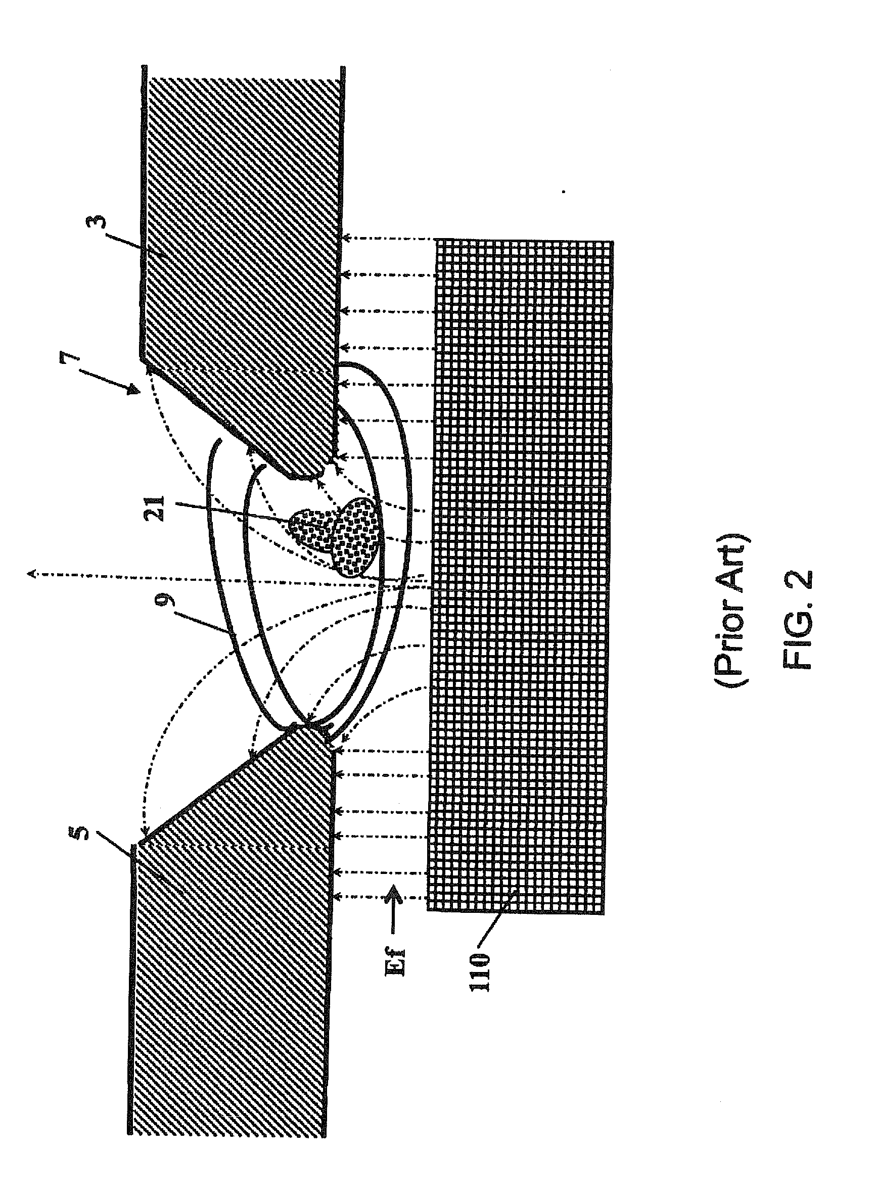
[0020]FIG. 1 illustrates a prior art ion source 100. Source 100 can either be annular or elongate and built to lengths that extend beyond three meters. Source 100 has a center pole magnet 4 and a soft iron pole system including back pole 1, side pole 2, outer pole 3 and inner pole 5. Source 100 extends inward and outward from the plane of the drawing figure to form either an annular or elongate ion source. Source 100 includes a racetrack shaped gap 7 between outer pole 3 and inner pole 5. An anode 11 is connected to the positive pole of DC power supply 15. A power supply 15 ground is connected to the cathode and the remaining ion source components. Anode 11 is electrically isolated from the poles and ground. In operation, when the power supply 15 is turned on and sufficient gas is present in gap regio...


PUM


Abstract

A closed drift ion source is provided comprising a single magnetic source, a first pole and a second pole. The ends of the first and second poles are separated by a gap. The magnetic source is disposed proximate to one of the first pole and second pole. A first magnetic path is provided between one magnetic pole of the single magnetic source and the end of the first pole. A second magnetic path is provided between the other magnetic pole of the single magnetic source and the end of the second pole. The first and second magnetic paths are selectively constructed to produce a symmetrical magnetic field in the gap.

Description

CROSS-REFERENCE TO RELATED APPLICATIONS[0001]This application claims priority of United States Provisional Patent Application Ser. No. 61 / 273,309 filed Aug. 3, 2009, which is incorporated herein by reference.FIELD OF THE INVENTION[0002]This invention pertains to in general an ion beam source, and in particular to a closed drift ion source.BACKGROUND[0003]Closed drift type ion sources are used today for a variety of industrial deposition, etching and surface modification applications. Closed drift type ion sources include both extended acceleration channel closed drift ion sources and anode layer type ion sources. Prior U.S. Pat. No. 6,919,672, by the same inventor as the present invention, provides a significant improvement over prior art ion sources by creating a balanced, symmetric magnetic field in the closed drift confinement region. In '672 the magnetic field is also shaped to confine electrons in the center of the confinement region. The innovations of '672 reduce the rate of ...

Claims


Application Information

Patent Timeline
IPC IPC(8): H05H1/46H01J27/02
CPCH01J27/143H01J2237/061H01J37/30H01J37/08
Inventor MADOCKS, JOHN E.
Owner MADOCKS JOHN E
Why Eureka
Try Eureka