
Simplified radio frequency receiver

a radio frequency receiver and simplified technology, applied in power management, radio transmission, electrical equipment, etc., can solve the problems of requiring at least doubling the radio size, requiring invasive surgery, and the replacement of a discharged battery may even require invasive surgery, so as to achieve a simple oscillator and reduce the amount of components needed. , the effect of efficient construction

Inactive Publication Date: 2012-07-19
AVAAK
View PDF3 Cites 3 Cited by
  • Summary
  • Abstract
  • Description
  • Claims
  • Application Information

AI Technical Summary

Benefits of technology

This approach enables smaller, more power-efficient radio modules, allowing for new applications and reducing the need for invasive battery replacements, thereby enhancing the proliferation of low-cost wireless communication devices.

Problems solved by technology

In addition to their communications and sensing circuits, these devices require a discrete and exhaustible power source (typically a battery) to operate.
In some cases, replacement of a discharged battery may even require invasive surgery.
The circuits are quite complicated and require at least doubling of the radio size.
Further, these receiver components consume power, thus contributing to shortened battery life.
This feature, combined with their inherent non-linearity, might result in injection locking, which is regularly observed in the laboratory.

Method used


Image

  • Simplified radio frequency receiver
  • Simplified radio frequency receiver
  • Simplified radio frequency receiver

Examples


Embodiment Construction

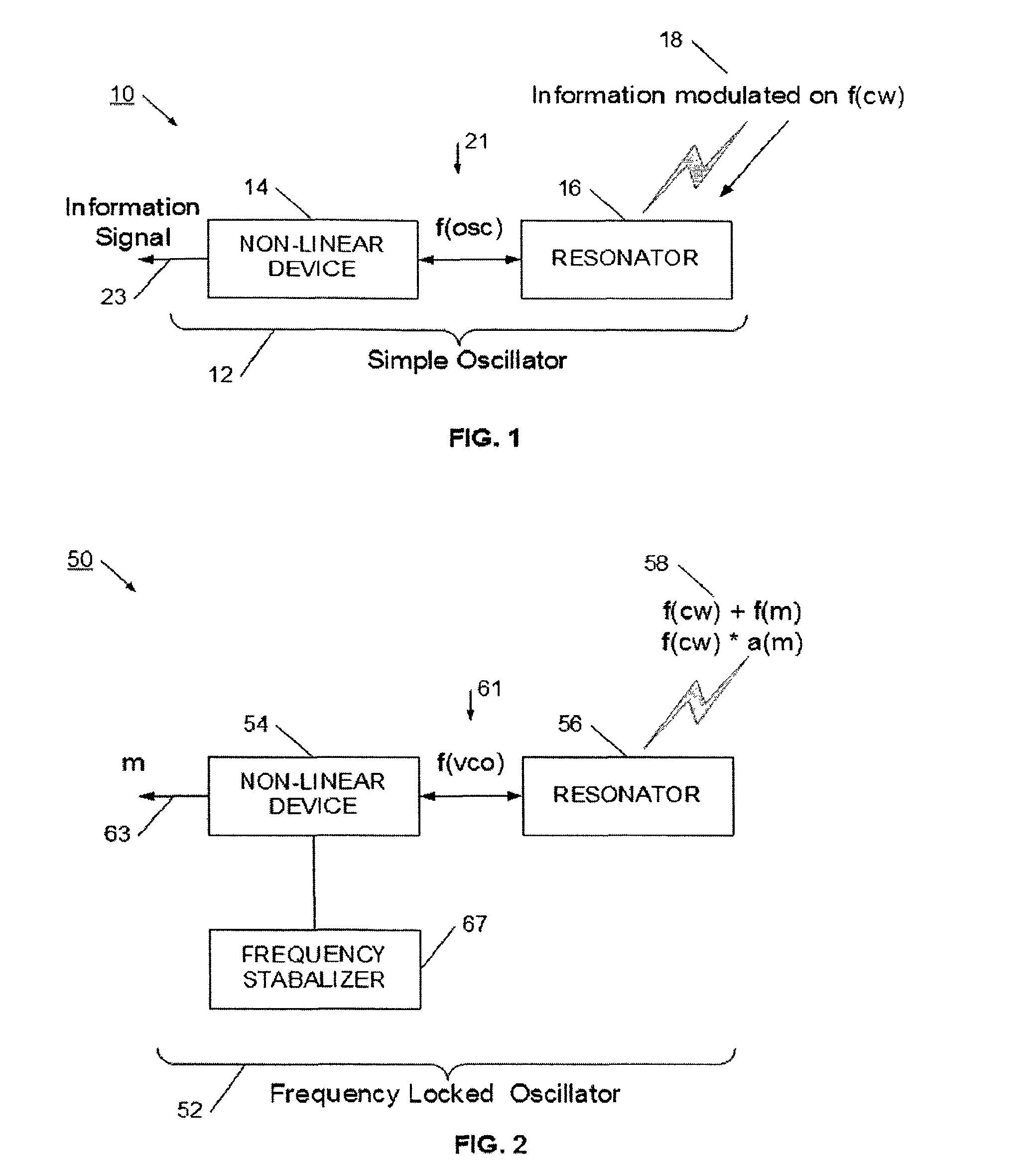
[0026]Referring now to FIG. 1, simplified receiver 10 is illustrated. Simplified receiver 10 is constructed to receive a modulated signal 18 and generate information signal 23. Modulated signal 18 typically has a carrier signal operating at f(cw), and has an information component modulated onto the carrier. The modulation method may be, for example, a frequency modulation, an amplitude modulation, a phase modulation, or other modulation process. Modulated signal 18 may be generated by a wireless transmitter attempting to send information to receiver 10. In its most basic form, receiver 10 is a simple oscillator 12 from which an information signal 23 may be directly extracted. As will be more fully described below, the simple and well known oscillator circuit may be arranged to operate as an active receiver device. Simple oscillator 12 may be a separate dedicated receiver device, or may be an oscillator which may selectively operate at one time as a receiver, and at another time, ope...


PUM


Abstract

An oscillator is provided that is arranged to function as a simplified receiver. The oscillator has a resonator portion and a non-linear portion, which cooperate to generate an oscillating signal. The resonator portion is positioned to receive a modulated signal. In one configuration, the oscillator operates at a frequency offset from the frequency of the carrier for the modulated signal. In this simple arrangement, the oscillator functions as an active mixer, and generates a product output signal. The output signal is extracted from a high impedance point of the oscillator's non-linear device. The output signal is a demodulated or mixed signal, and may be further processed to detect a data signal.

Description

RELATED APPLICATIONS[0001]The present invention is a continuation patent application of U.S. patent application Ser. No. 11 / 577,988, filed Apr. 25, 2007, now U.S. Pat. No. 8,145,139, issued Mar. 27, 2012, which is a U.S. Patent Application filed under 35 U.S.C. §371 as the U.S. national phase of International Application No. PCT / US2005 / 038443, filed Oct. 25, 2005, which designated the U.S. and claims the benefit of priority to U.S. Provisional Patent Application No. 60 / 621,619, filed Oct. 25, 2004, each of which is hereby incorporated in its entirety including all tables, figures and claims.FIELD OF THE INVENTION[0002]The field of the present invention is wireless receiver devices. More particularly, a wireless transceiver is disclosed for use in a wireless radio system.BACKGROUND[0003]The use of short-range miniature radios for communications has increased significantly in the last several years. With the widespread adoption of the Bluetooth standard, the introduction of network pr...

Claims


Application Information

Patent Timeline
Patent Type & Authority Applications(United States)
IPC IPC(8): H04B7/00
CPCH04W52/52H04B1/30
Inventor GOLDBERG, BAR-GIORA
Owner AVAAK
Learn More