
System and method for moving target detection

a detection system and target technology, applied in the field of detection, can solve the problems of manual selection, unknown number of clusters to input into the cluster algorithm, etc., and achieve the effect of reducing false alarms

Inactive Publication Date: 2012-07-19
ARMY US SEC THE
View PDF0 Cites 10 Cited by
  • Summary
  • Abstract
  • Description
  • Claims
  • Application Information

AI Technical Summary

Benefits of technology

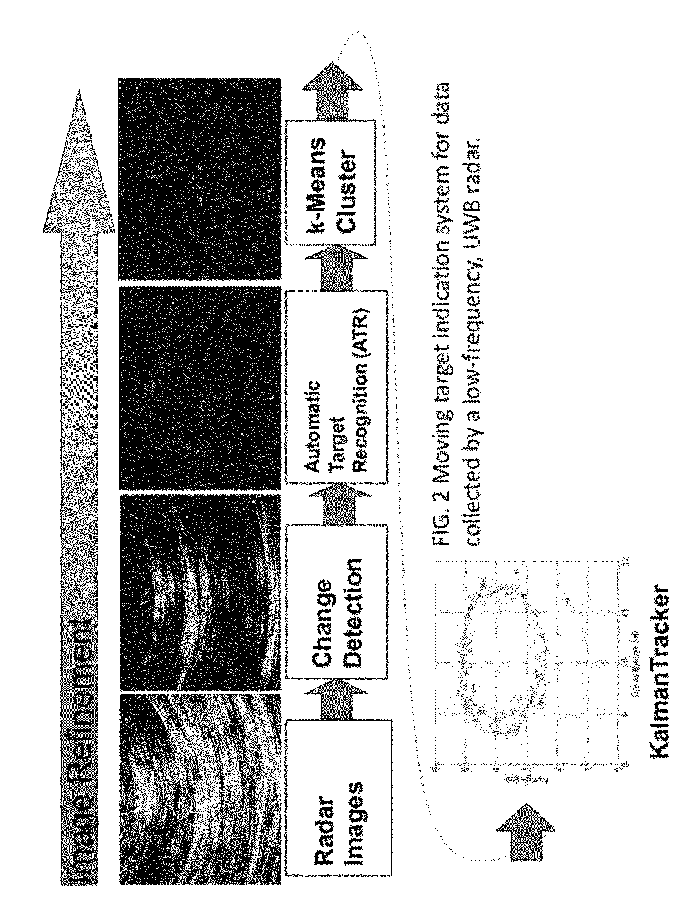
[0007]A preferred embodiment of the present invention comprises a cluster prediction algorithm for a system to automatically detect and track moving personnel inside buildings. The novel cluster prediction algorithm, inter alia, 1) automatically determines the number of clusters in an image (where each cluster corresponds to a potential moving target), 2) reduces false alarms, and 3) automates the entire moving target indication (MTI) system. This fully automated MTI system can be utilized to detect and track hostile personnel, enemy snipers, or hostages inside buildings. The MTI system could also be used for commercial applications that include: 1) law enforcement, 2) search and rescue, 3) building surveillance, 4) vehicle tracking on highways or in remote locations. The MTI system effectively combines several algorithms in a novel way to image slow and fast moving personnel from 6 m to 30 m inside building structures. The MTI system has successfully demonstrated detection capabilities of personnel walking inside wood and cinderblock buildings.
[0009]As reported in A. Martone, et al., “Clustering Analysis of Moving Target Signatures,” Proceedings of the SPIE Conference on Radar Sensor Technologies XIV, Orlando, Fla., April 2010 (hereby incorporated by reference) a cluster prediction algorithm has been developed. The cluster prediction algorithm i) automatically determines the number of clusters present in the binary images, ii) reduces false alarms in the binary images, iii) combines the first and second components of the MTI system thereby automating the entire MTI system. The cluster prediction algorithm is a novel, necessary, and unique contribution to the MTI system.
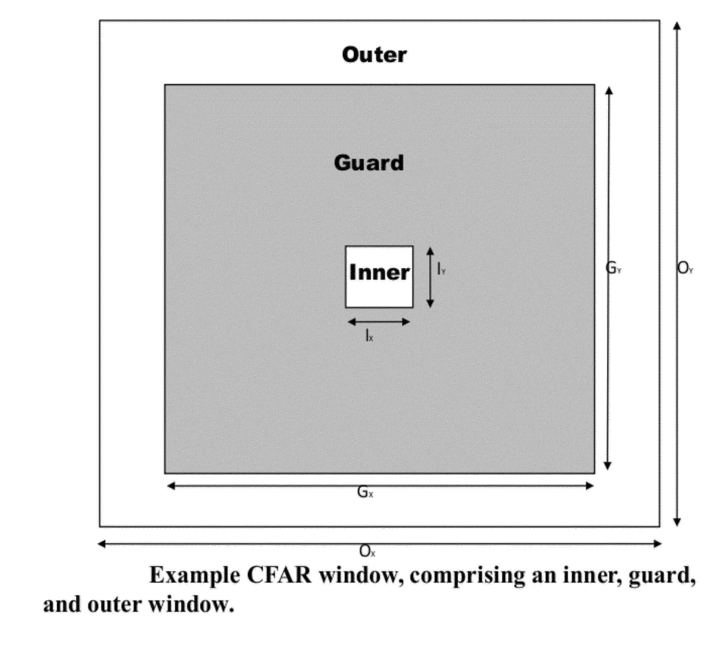
[0010]A preferred method of detecting moving targets comprises transmitting electromagnetic waves rays from a plurality of transmitters at sequential; receiving reflected waves into a plurality of receivers after each transmission; the compilation of the reflected waves from the plurality of receivers for each transmission representing a data frame; forming a signal that monitors changes between the two sets of frames; at least one processor operating to process and compare frames; forming a difference image using a back-projection algorithm; scanning the difference image using a constant false alarm rate (CFAR) window; the CFAR window scanning the entire difference image and identifying a list of points of interest and eliminating the sidelobe artifacts present in the difference image thereby creating CFAR images; processing the CFAR images using morphological processing to create a morphological image; determining the number of clusters present in the morphological image; using K-means clustering to indicate the centroid of each cluster; and tracking using a Kalman filter.

Problems solved by technology

Specifically, the number of clusters to input into the cluster algorithm is unknown and requires manual selection.

Method used


Image

  • System and method for moving target detection
  • System and method for moving target detection
  • System and method for moving target detection

Examples


Embodiment Construction

[0036]The embodiments herein and the various features and advantageous details thereof are explained more fully with reference to the non-limiting embodiments that are illustrated in the accompanying drawings and detailed in the following description. Descriptions of well-known components and processing techniques are omitted so as to not unnecessarily obscure the embodiments herein. The examples used herein are intended merely to facilitate an understanding of ways in which the embodiments herein may be practiced and to further enable those of skill in the art to practice the embodiments herein. Accordingly, the examples should not be construed as limiting the scope of the embodiments herein.

[0037]The preferred embodiment moving target indication (MTI) system is comprised of two main components. The first component detects potential moving targets by generating a time series of binary images that contain clusters. The second component of the MTI system tracks the centroid of each c...


PUM


Abstract

A system and method of detecting moving targets comprises transmitting electromagnetic waves rays from a plurality of transmitters at sequential; receiving reflected waves into a plurality of receivers after each transmission; the compilation of the reflected waves from the plurality of receivers for each transmission representing a data frame; forming a signal that monitors changes between the two sets of frames; at least one processor operating to process and compare frames; forming a difference image using a back-projection algorithm; scanning the difference image using a constant false alarm rate (CFAR) window; the CFAR window scanning the entire difference image and identifying a list of points of interest and eliminating the sidelobe artifacts present in the difference image thereby creating CFAR images; processing the CFAR images using morphological processing to create a morphological image; determining the number of clusters present in the morphological image; using K-means clustering to indicate the centroid of each cluster; and tracking using a Kalman filter. The system comprises a plurality of M transmitters, a plurality of receivers, and at least one memory, the transmitters operating in sequence to transmit electromagnetic waves rays sequentially; the receivers receiving reflected waves after each transmission; the compilation of the reflected waves from the plurality of receivers for each transmission representing a data frame; at least one processor operating to perform the method.

Description

STATEMENT OF GOVERNMENT INTEREST[0001]The embodiments herein may be manufactured, used, and / or licensed by or for the United States Government without the payment of royalties thereon.TECHNICAL FIELD[0002]The embodiments herein generally relate to detection, and more particularly, to detection of moving targets.BACKGROUND OF THE INVENTION[0003]Security and military forces operating in urban environments need the capability to detect slow moving personnel inside buildings. To identify moving personnel inside buildings, a time-domain approach may be used that uses a low-frequency, ultrawideband (UWB) radar. A low-frequency, UWB radar is desired since the low-frequency transmit pulse is capable of penetrating through the wall (1) and the UWB corresponds to a high range resolution that gives the capability to better locate the moving target (MT). The publication entitled “An Analysis of Clustering Tools for Moving Target Indication,” by Anthony Martone, Roberto Innocenti, and Kenneth Ra...

Claims


Application Information

Patent Timeline
Patent Type & Authority Applications(United States)
IPC IPC(8): G01S13/00
CPCG01S7/2923G01S13/0209G01S13/90G01S13/723G01S13/888G01S13/538G01S13/9029
Inventor MARTONE, ANTHONY F.RANNEY, KENNETH I.
Owner ARMY US SEC THE
Learn More