
Bone plate system for repair of proximal humeral fracture

a bone plate and humeral fracture technology, applied in the field of bone plate systems, can solve the problem that the amount of settling can often be significan

Active Publication Date: 2012-07-12
ASCENSION ORTHOPEDICS
View PDF21 Cites 15 Cited by
  • Summary
  • Abstract
  • Description
  • Claims
  • Application Information

AI Technical Summary

Benefits of technology

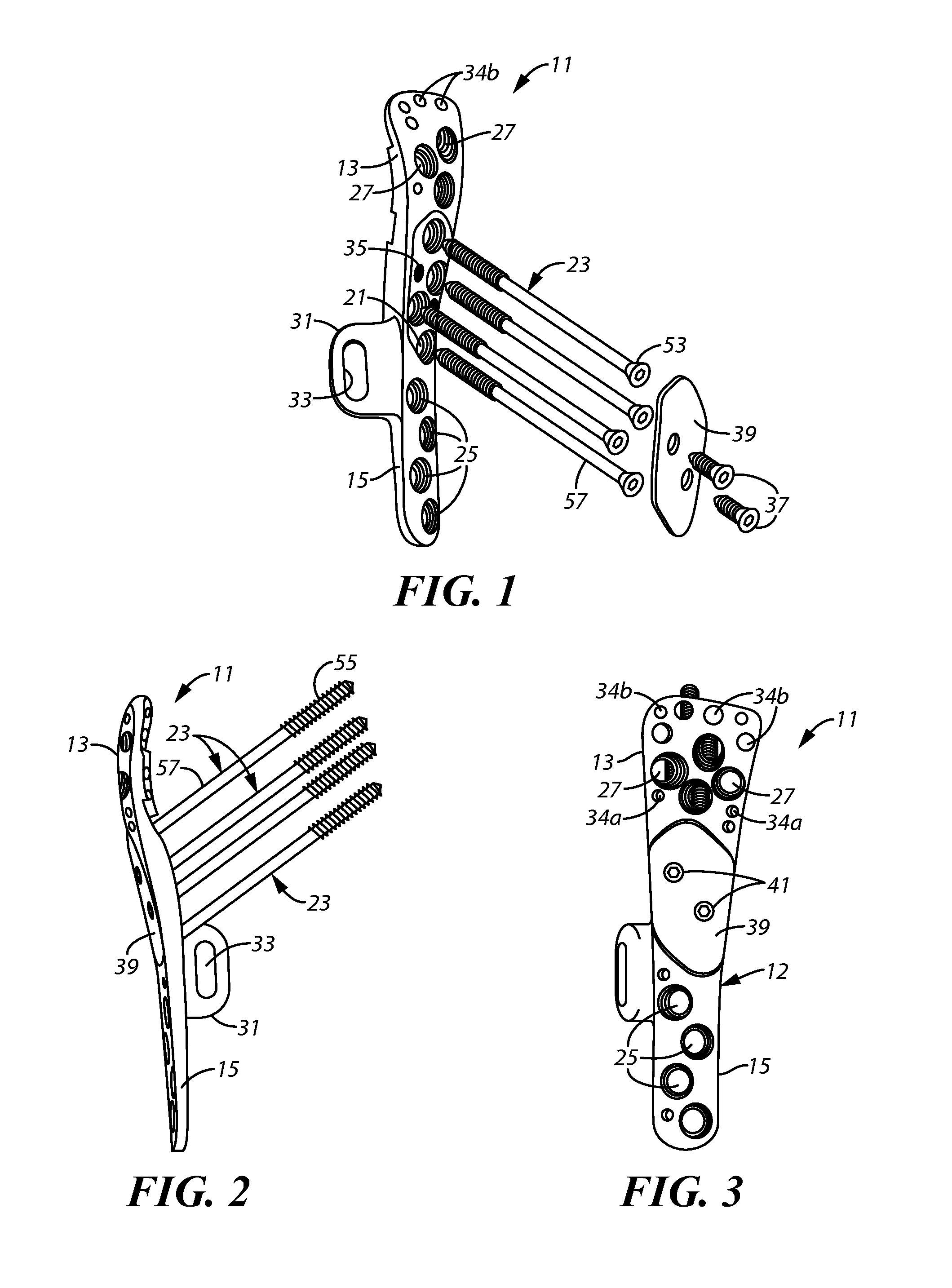
[0011]In another particular aspect, the invention provides a bone plate system for repair of a fracture of a major bone of the skeleton of a vertebrate, which system comprises a fixation plate having a main body including a head section and a stem section, which plate includes (a) a plurality of holes for passage therethrough of screws for fastening said fixation plate to the surface of an intact bone within which a fracture has occurred to create a fractured separate bone portion thereof and (b) a plurality of holes in said head section through which elongated compression screws can be passed which will extend through drilled passageways in the bone and screw into cortical bone of said fractured separate portion thereof, a plurality of fastening screws, a plurality of said elongated compression screws having threaded distal ends portions, and an integral stabilization flange which depends from said head section of said fixation plate and is aligned at an angle of about 70 degrees to 90 degrees thereto, which flange allows said fixation plate to be precisely aligned on the intact bone portion to facilitate precise placement of said elongated compression screws.

Problems solved by technology

A wide variety of mechanisms have been developed for locking these elongated compression screws to the fixation plate so as to prevent incidental subsequent movement of the screws that might result in screw back-out, which has been felt to be undesirable toward retaining the fractured section of the humeral head in alignment.
Over the years, it has been found that, during post-surgery, the fractured portion of the humeral head may frequently settle upon the closing of the fracture gap, and the amount of such settling can often be significant.

Method used


Image

  • Bone plate system for repair of proximal humeral fracture
  • Bone plate system for repair of proximal humeral fracture
  • Bone plate system for repair of proximal humeral fracture

Examples


Embodiment Construction

[0020]FIG. 1 shows a bone or fixation plate 11 designed particularly for treating a fracture of the proximal humerus, which is made of rigid material such as a biocompatible metal or metal alloy, e.g. titanium, stainless steel, titanium-aluminum-niobium alloys, etc. The fixation plate 11 has a main body 12 which comprises a head section 13 and stem section 15.

[0021]As best seen in FIG. 2, the fixation plate 11 is contoured so as to follow the general shape of the proximal end of the humerus, with the head section 13 lying juxtaposed with a surface of the humeral head and with the stem section 15 juxtaposed with a central elongated section of the humerus.

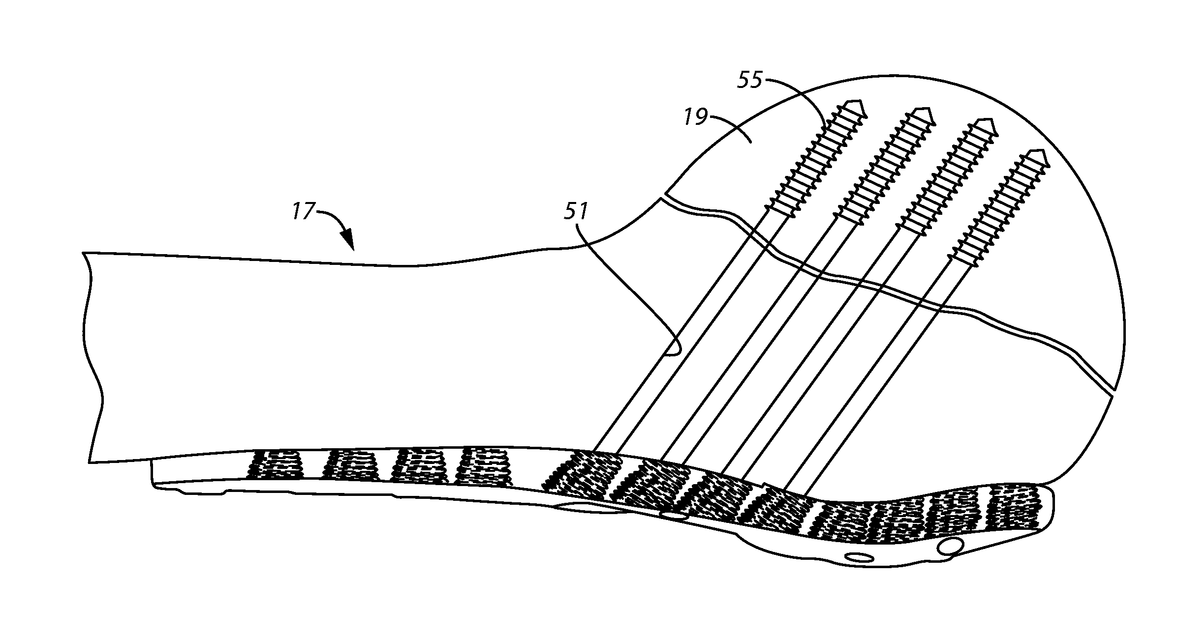
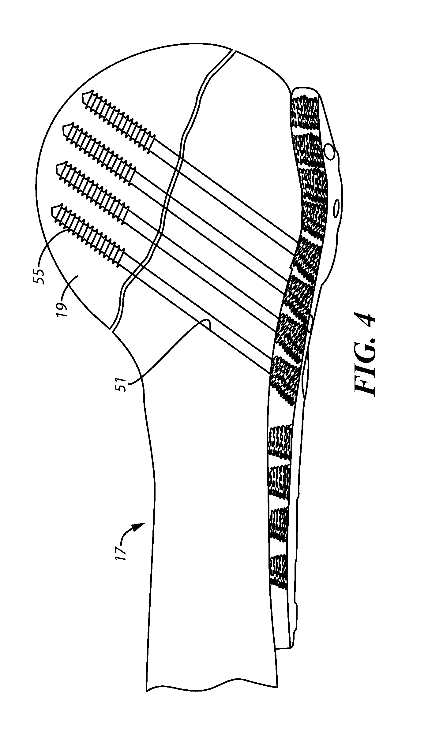
[0022]The fixation plate 11 is designed for treatment of a fracture of the humerus 17 where a portion 19 of the head of the humerus has been fractured and separated from the remainder of the bone. FIG. 4 depicts such a repair of a humeral head fracture showing the proximal end region of the humerus 17 and the fractured portion of the...


PUM


Abstract

A bone plate system for repair of a proximal humeral head fracture, which includes a fixation plate having a main body and a depending alignment flange, a plurality of elongated compression screws to extend through the intact humeral head into the cortical bone of the fractured portion and a cover plate. With the fixation plate in place, fastened to the humerus, the cover plate is in turn fastened to the fixation plate and provides a defined amount of clearance in a region adjacent the heads of the compression screws to allow measured back-out of the screws upon settling of the fractured bone portion at the fracture site.

Description

[0001]This application claims priority from U.S. Provisional Patent Application Ser. No. 61 / 431,258, filed Jan. 10, 2011, the disclosure of which is incorporated herein by reference.FIELD OF THE INVENTION[0002]The present invention relates to orthopedic products for repair of fractured bones and more particularly to bone plate systems for repair of a major bone of the skeleton of a vertebrate, such as a proximal humeral head fracture.BACKGROUND OF THE INVENTION[0003]Fractures of the proximal humerus can occur in patients of any age; however, these fractures have been found to occur more frequently in older patients, particularly elderly females who may suffer from osteoporosis. Such fractures usually occur in predictable fracture patterns and are commonly caused by falls where an arm was outstretched in an attempt to break the fall. Due to the compressive and varus forces about the shoulder, there is a tendency for the humeral head fragment to collapse in varus and settle distally.[...

Claims


Application Information

Patent Timeline
IPC IPC(8): A61B17/80
CPCA61B17/8042A61B17/8057A61B17/8625A61B17/8061
Inventor GEISSLER, WILLIAM B.ESTRADA, LINDA C.
Owner ASCENSION ORTHOPEDICS
Learn More