
Systems and Methods for Protection from Explosive Devices

a technology of electromagnetic jammer and system, applied in the field of electromagnetic jammer system testing and rapid fielding, can solve the problems of difficult to envision what kind of bomb will be used next and how to protect against, and the jamming is not without limitations, so as to achieve the effect of minimizing destructive spaces

Inactive Publication Date: 2012-07-12
MAV6 LLC
View PDF10 Cites 5 Cited by
  • Summary
  • Abstract
  • Description
  • Claims
  • Application Information

AI Technical Summary

Benefits of technology

[0014]Furthermore, results from accurate and validated simulators assist in deriving algorithms for determining safe vehicle / troop formations in exemplary embodiments of the present invention. Military personnel use the safe formations to minimize destructive spaces created by interference from multiple RF jammers. The safe formations are used to guide military personnel into desired positions consistent with the safe formation. In some instances, GPS locators are used to give accurate direction. Military drivers are provided graphical indicators of a desired position versus an actual position and visual and audible warnings upon significant deviation from a desired position.

Problems solved by technology

Funding to these groups can be limited, so they improvise with available materials.
For this reason it is very hard to envision what kind of bomb will be used next and how to protect against it.
However, such jamming is not without its limitations, as multiple triggering devices with multiple waveforms may exist in any given geographical area.
For a vehicle equipped with one of these devices on its own, a combatant signal is generally jammed within a given safety zone extending outward from the CREW system.
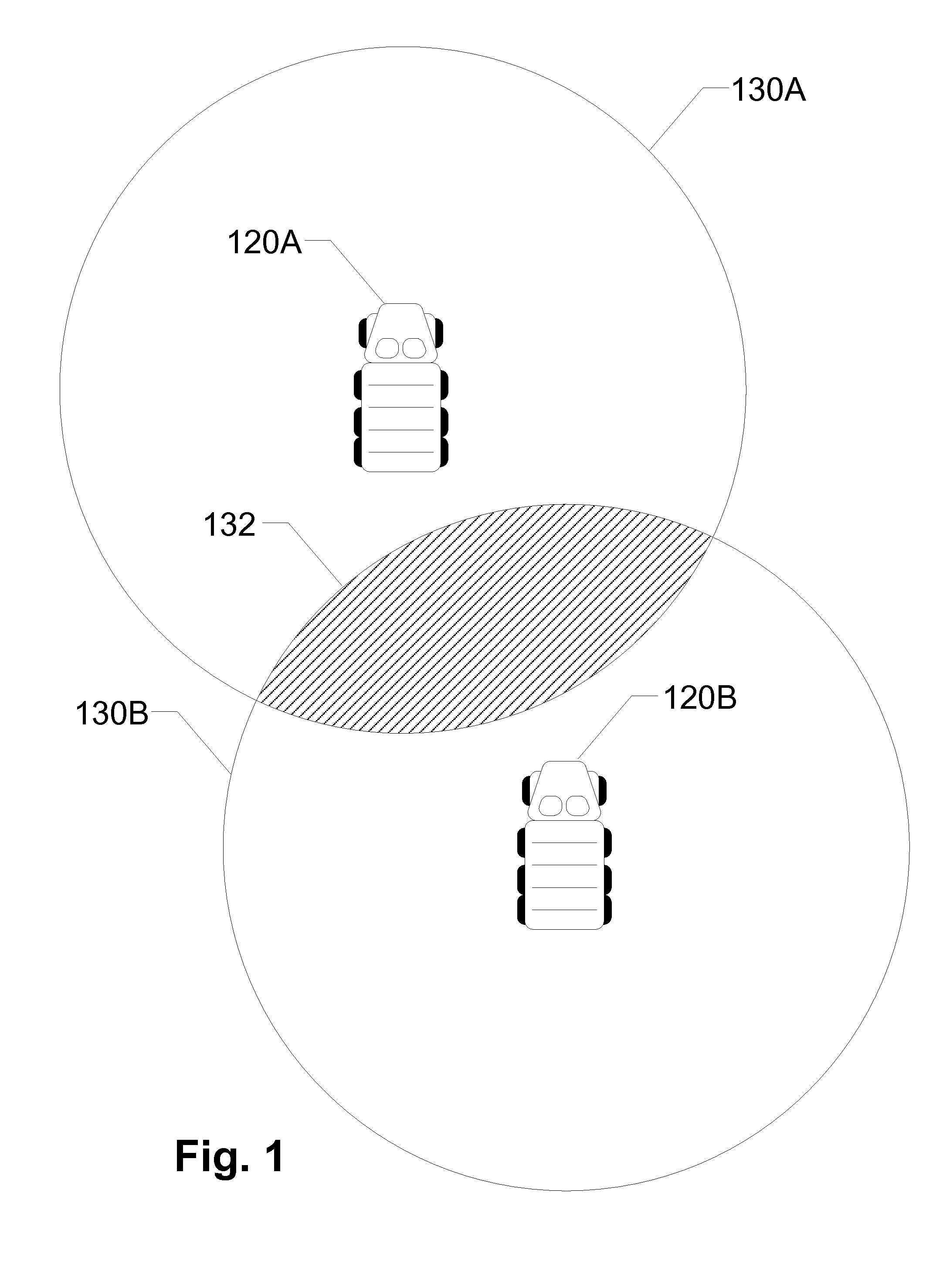
With multiple CREW emitters in proximity to one another, the result is constructive and destructive interference spaces in the resultant field as well as interference with on-board “friendly” electronics and communications systems.
So, for instance, with a 50 vehicle convoy with multiple vehicles outfitted with CREW systems, electromagnetic interference problems occur.
This is even more complex as a change to the location of metal on a vehicle or the location of a CREW system antenna affects the emitted field, often in a major fashion.
This may result in large gaps in the field of protection for that vehicle and those vehicles in proximity.
Further, the variations introduced by environmental factors add another dimension to the testing problem.
Actually executing all these tests would require an extraordinary amount of time and would be prohibitively costly.
Thus, both the cost factor and the lengthy time to execute make the current testing method and approach not feasible to meet the urgent need for these and similar vehicles in the theater.
The result is that the vehicles and their systems are not as extensively tested as would be preferred so that they may be shipped to theater quickly, or the vehicle testing is executed completely and the vehicles delivered far too late to be effective.
Since the latter is not really an operational option, partial testing can potentially lead to convoy configurations that experience intermittent gaps in the coverage field.
Operators would be unaware of these configurations and situations and would behave as though they are protected when it turns out that large sectors around them are completely uncovered, leaving them vulnerable.
Varying speeds only slightly may cause coverage gaps in different places.
When the vehicle spacing changes, the field pattern changes such that a space on or along the edge of the road that may have been protected for the first part of the convoy suddenly ends up with a gap in the jamming coverage.
If an IED were to be placed at the point where the gap appears, as soon as the jamming strength falls sufficiently, the IED can explode and cause casualties.

Method used


Image

  • Systems and Methods for Protection from Explosive Devices
  • Systems and Methods for Protection from Explosive Devices
  • Systems and Methods for Protection from Explosive Devices

Examples


Embodiment Construction

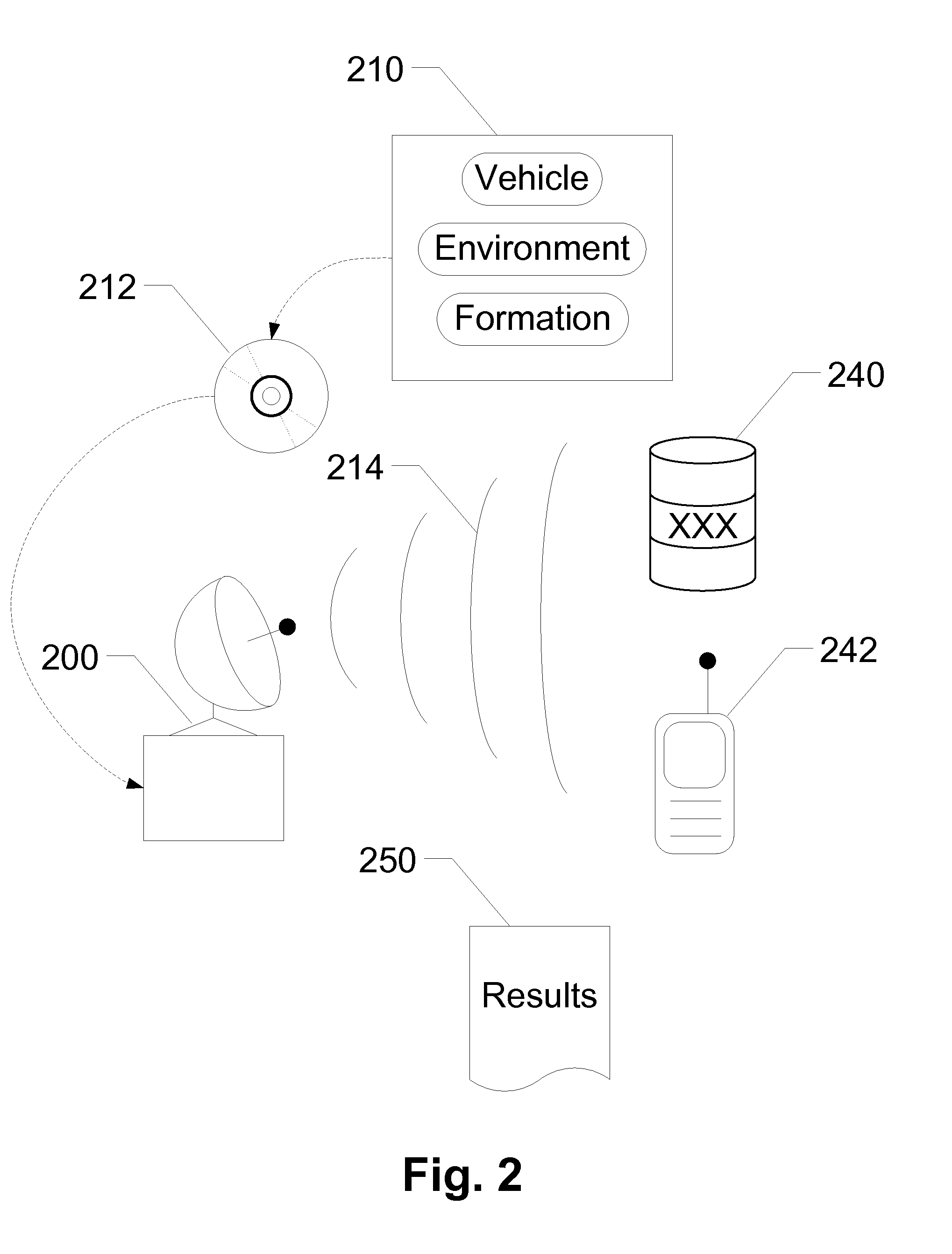
[0027]The present invention presents systems and methods for reproducing and testing a simulation of electromagnetic propagation of multiple Radio Frequency (RF) jammers in an environment to determine the effectiveness of the jammer configuration. In exemplary embodiments of the present invention a multi-jammer simulator renders the electromagnetic propagation of a multiple jammer scenario including multiple RF jammers onboard vehicles traveling through the environment, and records a multi-waveform output of the multiple jammer scenario to a recordable medium. A multi-waveform generator reads the multi-waveform output from the recordable medium and physically reproduces a plurality of waveforms consistent with the multi-waveform output. The plurality of waveforms is substantially similar to a physical reproduction of the multiple jammer scenario. An RF receiver, placed within a range of effectiveness of the multi-waveform generator, attempts to receive a signal from an RF transmitte...


PUM


Abstract

Devices, systems and methods are disclosed which relate to reproducing and testing a simulation of electromagnetic propagation of multiple Radio Frequency (RF) jammers in an environment to determine the effectiveness of the jammer configuration. In some configurations, a multi-jammer simulator renders the electromagnetic propagation of a multiple jammer scenario, including multiple RF jammers onboard vehicles traveling through the environment, and records a multi-waveform output of the multiple jammer scenario to a recordable medium. A multi-waveform generator reads the multi-waveform output from the recordable medium and physically reproduces a plurality of waveforms consistent with the multi-waveform output. The plurality of waveforms is substantially similar to a physical reproduction of the multiple jammer scenario. An RF receiver, placed within a range of effectiveness of the multi-waveform generator, attempts to receive a signal from an RF transmitter during reproduction of the multi-waveform output. Results are recorded in the form of successes and failures associated with the attempts and compared with results from the simulation.

Description

[0001]This application claims priority to U.S. Provisional Patent Application Ser. No. 61 / 142,089, filed Dec. 31, 2008, the content of which is hereby incorporated by reference in its entirety into this disclosure.BACKGROUND OF THE INVENTION[0002]1. Field of the Invention[0003]The present invention relates to the testing and rapid fielding of electromagnetic jammer systems. More specifically, the present invention relates to determining the effectiveness of jammer configurations.[0004]2. Background of the Invention[0005]Today's combat zones are very different than in any past conflict. Today's combat zones are asymmetrical with enemy combatants that avoid direct and open engagement, preferring instead to engineer improvised traps. Led by guerillas or commandos, these enemies often do not wear uniforms or march in lines, but are instead scattered and blend in with the general population of an area. Funding to these groups can be limited, so they improvise with available materials.[00...

Claims


Application Information

Patent Timeline
IPC IPC(8): G01S7/38
CPCG01S7/38H04K3/44H04K3/92H04K2203/34H04K2203/16H04K2203/22H04K2203/24H04K3/94
Inventor HOLTON, JAMES JEROMEBALLARD, BRIAN A.KLUESENER, ROBERT D.
Owner MAV6 LLC
Learn More