
Vehicle for launching from a gas gun

a gas gun and rocket technology, applied in the direction of rockets, instruments, cosmonautic vehicles, etc., can solve the problems of reducing the amount of propellant needed, the cost of about $5,000 per lb of payload delivered, and the initial velocity of the rocket is extremely high, so as to reduce the amount of propellant needed, the effect of increasing the fraction of payload to orbit and increasing the initial velocity

Active Publication Date: 2012-07-12
QUICKLAUNCH
View PDF32 Cites 20 Cited by
  • Summary
  • Abstract
  • Description
  • Claims
  • Application Information

AI Technical Summary

Benefits of technology

The technology described in this patent allows for a space vehicle to have more speed when it takes off from a gun compared to traditional rockets, which means less fuel is required and can carry more payloads into space.

Problems solved by technology

The technical problem addressed in this patent is how to launch projectiles like missiles at lower costs and increased efficiency compared to traditional rockets.

Method used


Image

  • Vehicle for launching from a gas gun
  • Vehicle for launching from a gas gun
  • Vehicle for launching from a gas gun

Examples


Embodiment Construction

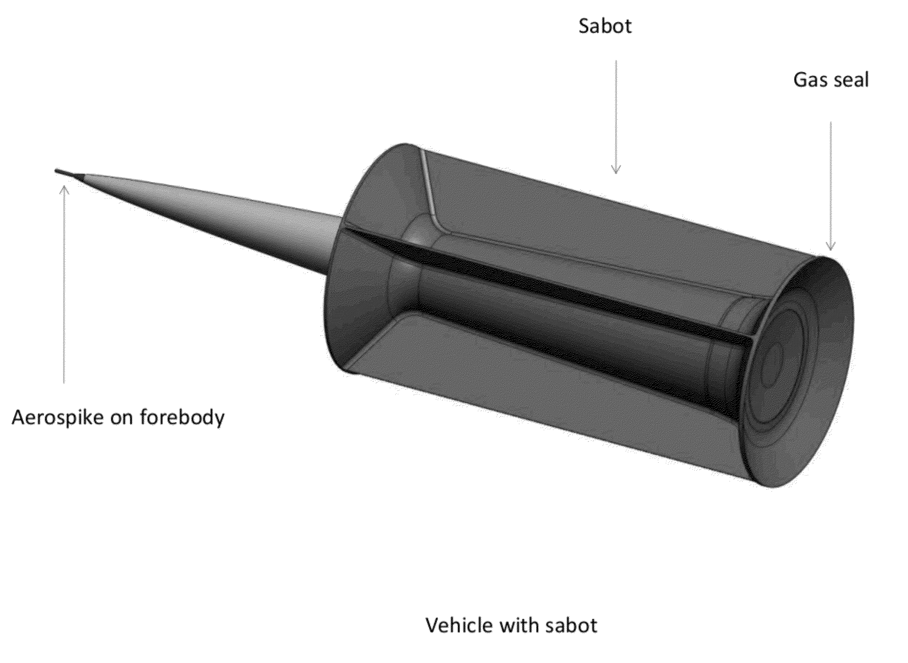
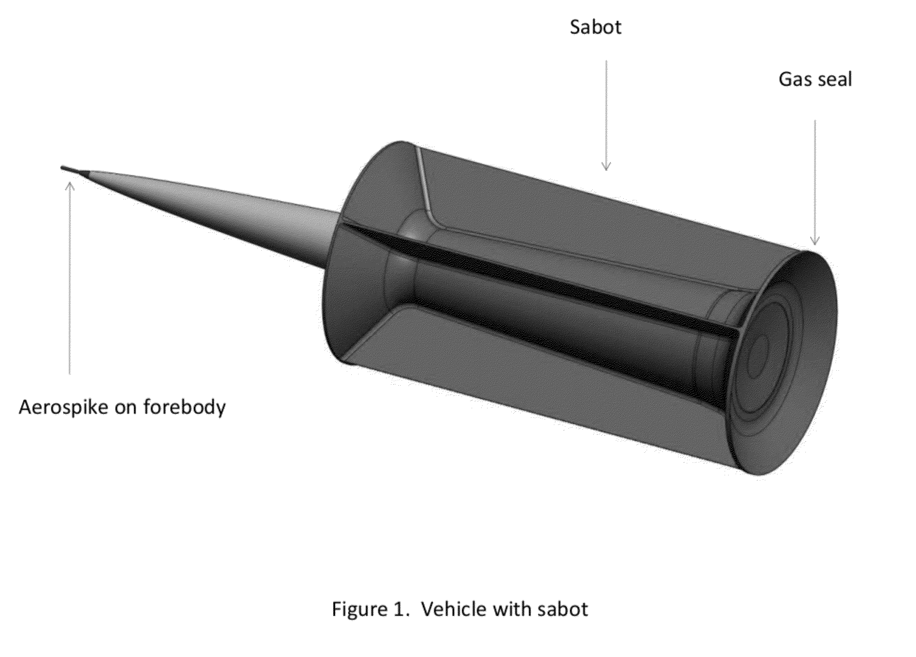
[0024]The launch vehicle, illustrated in FIGS. 1 through 6, has a sabot that encloses the aero-shell and gives it an effectively larger area. The sabot is preferably composed of at least two petals, even more preferably of two to six petals, and most preferably of four petals. The petals are a composite or aluminum and fall off of the aero-shell when the vehicle emerges from the launcher and encounters aerodynamic forces.

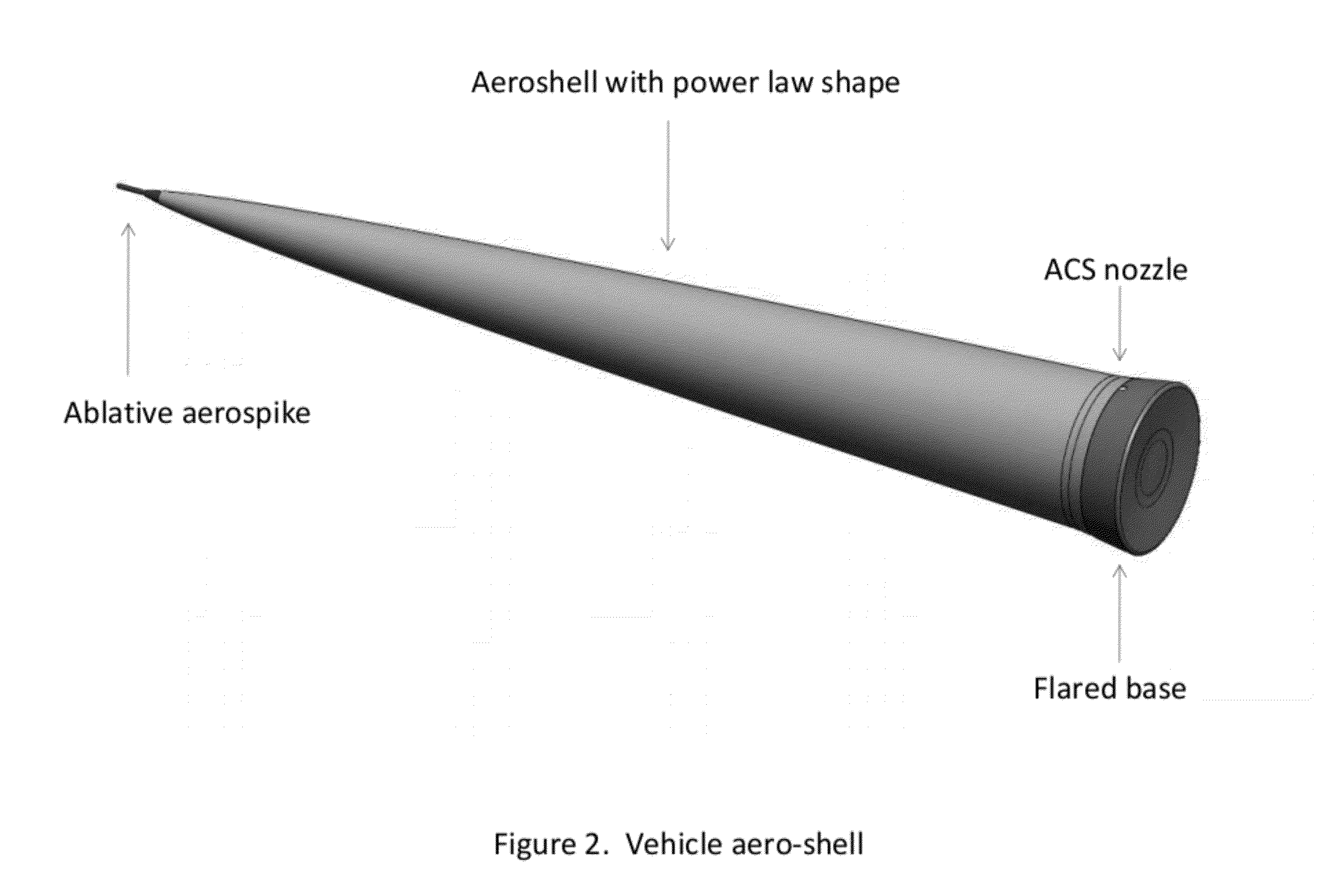
[0025]The aero-shell preferably has a power law shape of the form r=AXP where the exponent is 0.75, although other viable shapes such as bi-conic exist. The acceptable range of exponent is, though, between 0.25 and 1.5, inclusive. The length to diameter ratio L / D is between 3 and 20, exclusive of the endpoints. An L / D of 5 has about 4 times the drag of an L / D of 10. The reason for excluding L / Ds greater than or equal to 20 is the fragility of long skinny objects at extreme speeds in air. Conversely, an L / D of 1, will be rugged but have unacceptably high drag.

[0026]T...


PUM


Abstract

A vehicle for launching from a gas gun having a housing; preferably incorporating a precessional attitude control system; and utilizing a flared base, fins, or active use of the attitude control system during passage through the atmosphere. Subtly canting the fins can produce desired spinning of the vehicle. The propulsion system can employ liquid, hybrid, or solid fuel. A removable aero-shell assists atmospheric flight with thermal protection being provided by anticipated ablation, an ablative aero-spike, or transpirational cooling. And a releasable sabot enhances the effectiveness of the launch.

Description


Claims


Application Information

Patent Timeline
Owner QUICKLAUNCH
Learn More