
Clock Operated Step Function Solar Tracker

a solar tracker and step function technology, applied in the field of clock operated step function solar trackers, can solve the problems of high cost, high cost, and large over-sizing of fixed panel systems, and achieve the effects of reducing cost, good energy capture performance, and superior performan

Inactive Publication Date: 2012-07-12
THOMPSON BRUCE A
View PDF5 Cites 6 Cited by
  • Summary
  • Abstract
  • Description
  • Claims
  • Application Information

AI Technical Summary

Benefits of technology

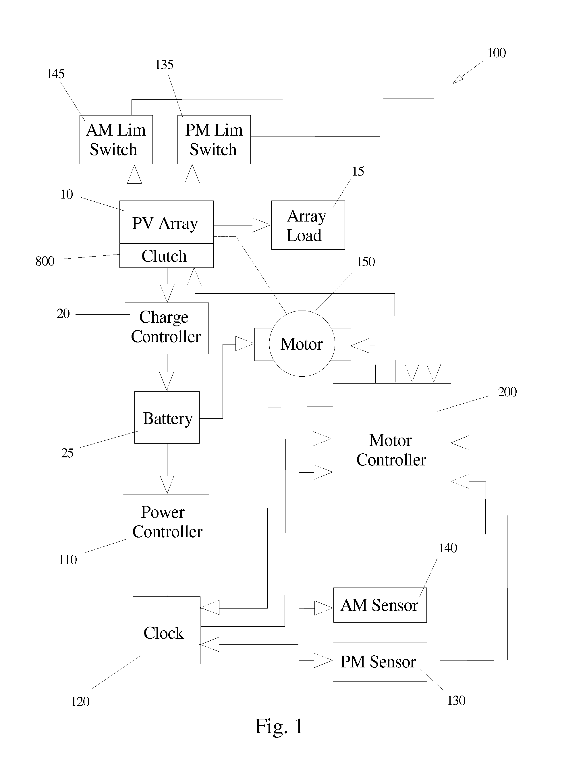
[0012]The present invention describes a solar panel system tracker that closely approximates the output levels of an actively tracked system but at significantly reduced levels of complexity and cost. The present invention utilizes a clock that generates a five degree step function which moves the solar panel system in five degree increments over the period of the solar day. This provides approximately thirty-five separate adjustments throughout the day, yielding an aggregate output performance of approximately 90 percent compared to a fully tracked system.
[0014]The clutch used in the present invention is a coaxial friction clutch formed by a pair of disks: a fixed disk, or lower clutch plate, and a movable disk, or upper clutch plate, that is free to rotate on top of the lower clutch plate. The fixed disk has stop holes drilled at five degree increments, into which a pin controlled by a solenoid drops once a given step has occurred. This pin-and-hole combination is used to provide the requisite stability under windy conditions.
[0015]The coaxial friction clutch assembly attaches to a fixed post via the lower fixed disk. The solar panel system, mounted on a frame, attaches to one end of a panel boom. The center of the panel boom attaches to the moveable disk. A counterweight is attached to the end of the panel boom opposite the solar panel system to create a balance point that is centered over the center of the moveable disk, thereby minimizing the load on the motor.
[0017]The method and apparatus of the present invention offer several advantages over the prior art. Among these are much lowered cost, good energy capture performance when compared to actively tracked systems and superior performance when compared with fixed systems. As well as these advantages, the present invention has other advantages discussed in detail below in conjunction with the drawings and figures attached.

Problems solved by technology

Any off angle, whether longitudinal or lateral, will result in a rapid decline of the output power.
The over-sizing of a fixed panel system is highly inefficient and very costly.
The focusing method suffers from two serious problems.
First, focusing methods cause a buildup of heat on the surface of the panel or target, thus raising the junction temperature of the individual cells.
This causes a decrease in output simply due to semiconductor physics.
This is expensive and complex.
Second, while the focusing method increases the output with respect to a fixed panel system, unless it is tracked it, too, has inefficiencies for the same reasons discussed just above.
Tracking methods also suffer from multiple problems.
First, they are complex, requiring specialized knowledge to install and maintain.
Second, they are very expensive.
Third, in general they exhibit a high failure rate when compared with the other methods described.
This is due to the complex mechanisms, use of exotic substances and difficulty in maintaining alignment under certain conditions.

Method used


Image

  • Clock Operated Step Function Solar Tracker
  • Clock Operated Step Function Solar Tracker
  • Clock Operated Step Function Solar Tracker

Examples


Embodiment Construction

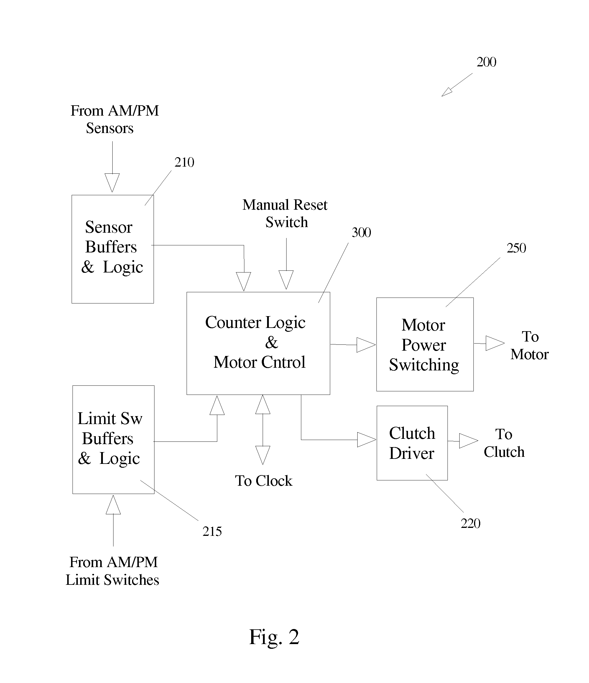
[0027]The method and apparatus of the present invention form a system for economically optimizing the amount of energy captured from the sun using a solar panel array. Each of the various components of the apparatus will be discussed in detail in following paragraphs; however, a review of FIG. 6 will provide an understanding of the basic architecture of the system.

[0028]Looking briefly at FIG. 6, the apparatus of the present invention is comprised of three major parts: an array of solar panels 10, a coaxial friction clutch assembly 800, and an array boom 950 and counterweight assembly 900. Generally, the solar panel array 10 faces the sun and converts incoming light energy to direct current electrical energy. Coaxial friction clutch assembly 800 serves a number of purposes including acting as a mounting platform for the control electronics and battery as well as providing the wind stabilized pivot point needed for tracking the sun during a typical solar day. The array boom and count...


PUM


Abstract

The present invention describes a solar panel system tracker that closely approximates the output levels of an actively tracked system but at significantly reduced levels of complexity and cost. The present invention utilizes a clock that generates a five degree step function which moves the solar panel system in five degree increments over the period of the solar day. This provides approximately thirty-five separate adjustments throughout the day, yielding an aggregate output performance of approximately 90 percent compared to a fully tracked system.

Description

[0001]This continuation-in-part contains all of an earlier filed non-provisional application Ser. No. 12 / 290,511, filed Nov. 1, 2008.BRIEF DESCRIPTION[0002]The subject of this invention relates to the alternative energy arts. Specifically, the present invention discloses a solar tracker that operates on the principle of a clock operated step function which provides energy capture performance of near real time tracking systems but at a very economical cost.BACKGROUND OF THE INVENTION[0003]Power generation by means of photovoltaic cells (PV) is not new. Individual cells are normally configured in an array of multiple cells to create a specific desired output power. For example, a series / parallel array to provide and output rating of 12 volts at 1.5 amps. This series / parallel arrangement is referred to as a “solar panel,” and power output from the panel is customarily expressed in watts, thus in the preceding example the panel formed by the array would have a nominal rating of 18 watts...

Claims


Application Information

Patent Timeline
IPC IPC(8): H01L31/052
CPCF24J2/38F24J2002/5493F24J2002/5496H02S20/00Y02E10/50F24J2/5403Y02E10/47G01S3/7861F24S30/42F24S50/20F24S2030/18F24S2030/19H02S20/32
Inventor THOMPSON, BRUCE A.
Owner THOMPSON BRUCE A
Learn More