
Asynchronous transmission with double wake up

a technology of asynchronous transmission and wake up, applied in the field of system, apparatus, method and computer program product for controlling asynchronous transmission of communication signals, can solve the problems of long operation life even from a small form factor battery, overhead power consumption both in transmission and reception, and achieve the effect of being particularly power efficien

Active Publication Date: 2012-07-05
KONINKLIJKE PHILIPS ELECTRONICS NV
View PDF5 Cites 38 Cited by
  • Summary
  • Abstract
  • Description
  • Claims
  • Application Information

AI Technical Summary

Benefits of technology

[0008]An object of the present invention is to provide an improved transmission system that is particularly power efficient for receiving devices in asynchronous operation modes.

Problems solved by technology

In this mode the devices spend most of their time sleeping, potentially resulting in long operational life even from a small form factor battery.
The preamble introduces a power consumption overhead both in transmission and in reception.
However, in a low power, low duty cycle network it is typical that most devices spend the vast majority of their time receiving, and only transmit occasionally.

Method used


Image

  • Asynchronous transmission with double wake up
  • Asynchronous transmission with double wake up
  • Asynchronous transmission with double wake up

Examples


first embodiment

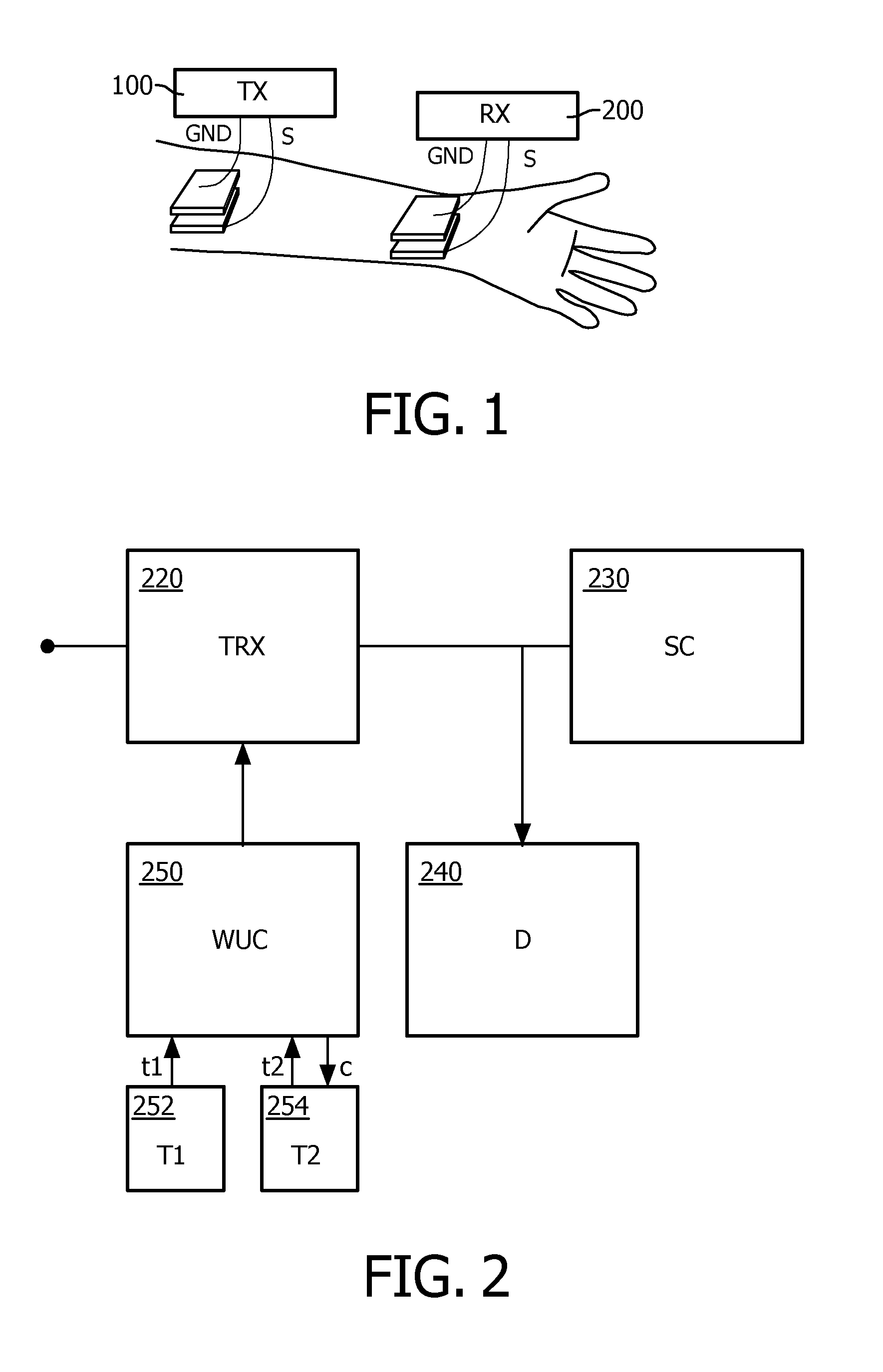
[0030]In the first embodiment, the wake up controller 250 controls the start of the second timer circuit 254 by a control signal c.

[0031]In the following, a double wake up control by the wake up controller 250 is described in more detail.

[0032]A transmitter of the concerned BAN transmitter sends a near constant sequence of wake up messages (e.g. WUPs), each wake up messages being preceded by a preamble. Based on the wake up schedule, the wake up controller 250 activates the receiver or receiving operation of the TRX 220 and triggers a timer operation of the first timer circuit 252. Thus, the detector circuit 240 checks, for the short time period counted by the first timer 252, for a preamble in the received signal. In case the detector 240 indicates that a preamble has been detected, the wake up controller 250 controls the receiver of the TRX 220 to stay on so as to listen for the entire wake up message.

[0033]Otherwise, if the detector circuit 240 does not detect any preamble in the...

second embodiment

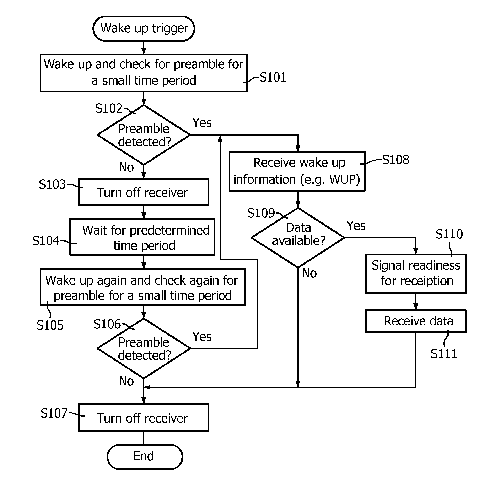
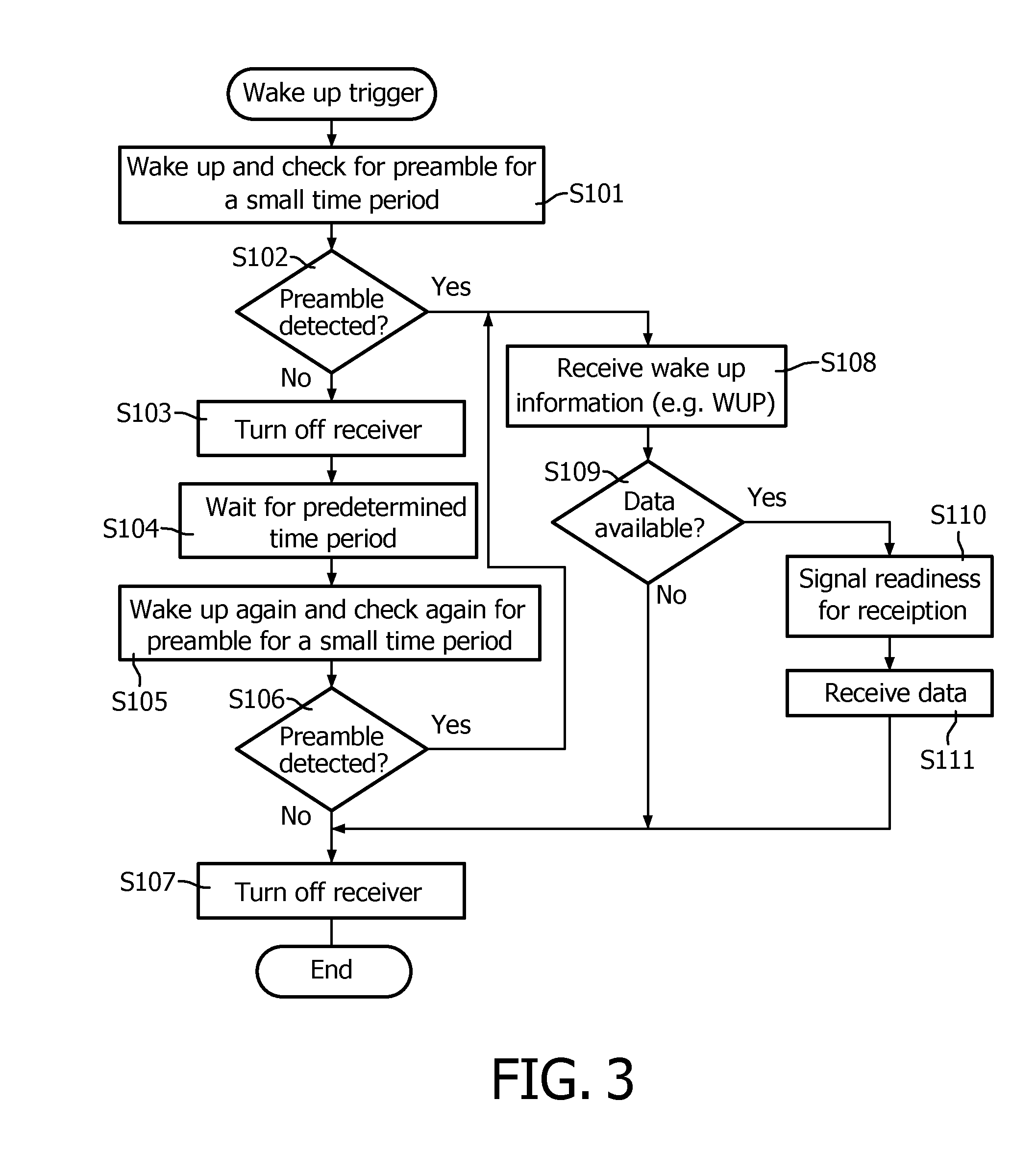
[0038]FIG. 3 shows a schematic flow diagram of a wake up control procedure according to a This procedure may be implemented in the wake up controller 250 of FIG. 2.

[0039]The procedure of FIG. 3 is initiated or triggered by a wake up trigger which may be generated during every cycle of a wake up schedule.

[0040]In step S101 the receiver is activated or woken up and a check for the preamble of a wake up message or command is performed for a small time period sufficient to detect the preamble. In step S102 it is checked whether a preamble has been detected during the small checking period.

[0041]If it is determined in step S102 that a preamble has not been detected, the procedure continues with step S103 and the receiver is turned off. Then, in step S104, an intermediate waiting period is introduced with a predetermined length to ensure that a preamble, if transmitted, will be received after this waiting period. Accordingly, in the subsequent step 5105, the receiver is reactivated or wo...


PUM


Abstract

The present invention relates to an apparatus, method and computer program product for controlling reception in an asynchronous operation mode, wherein a transmitter sends an extended preamble sequence of length longer than the maximum length of a wake up message itself plus the maximum length of a gap between wake up messages, such that a receiver turning on during a sequence of wake up commands and not detecting the wake up commands, can be sure to successfully detect a preamble if it tries again a second time a set interval later.

Description

FIELD OF THE INVENTION[0001]The present invention relates to a system, apparatus, method, and computer program product for controlling asynchronous transmission of communication signals, such as—but not limited to—body-coupled communication signals.BACKGROUND OF THE INVENTION[0002]Body-coupled communications (BCC) or body-based communication has been proposed as a promising alternative to radio frequency (RF) communication as a basis for body area networks (BANs) as standardized by the 802.15.6 Task Group of the Institute of Electrical and Electronics Engineers (IEEE). BCC allows exchange of information between a plurality of devices which are at or in close proximity of a body of a human or an animal. This can be achieved by capacitive or galvanic coupling of low-energy electric fields onto the body surface. Signals are conveyed over the body instead of through the air. As such, the communication is confined to an area close to the body in contrast to RF communications, where a muc...

Claims


Application Information

Patent Timeline
IPC IPC(8): H04W52/02H04B5/00
CPCH04W52/0225H04B13/005Y02D30/70H04B13/00H04W52/02
Inventor RUDLAND, PHILIP ANDREWPATEL, MAULIN DAHYABHAIJAMIESON, PHILIP ANTHONY
Owner KONINKLIJKE PHILIPS ELECTRONICS NV
Learn More