
Synthetic jet packaging

Inactive Publication Date: 2012-07-05
GENERAL ELECTRIC CO
View PDF13 Cites 45 Cited by
  • Summary
  • Abstract
  • Description
  • Claims
  • Application Information

AI Technical Summary

Benefits of technology

[0041]Technical effects of the invention include combining a connector, membranes, and power electronics, within a single housing. Accordingly, the device may cool an existing system, preventing the redesign of the system to include synthetic jets. Furthermore, because the device includes all the components within a single housing, it may be easily replaced when broken or used. Finally, the device advantageously uses the housing surfaces in combination with the membranes to form additional synthetic jets.

Problems solved by technology

Microchips, LEDs, radio frequency components, memory chips, and other electronic devices may generate a significant amount of heat during use.
At times, the environment surrounding the electronic devices may be unable to provide the necessary cooling.
When including a cooling device to assist in heat removal, the cooling device itself may introduce a number of additional design challenges.

Method used


Image

  • Synthetic jet packaging
  • Synthetic jet packaging
  • Synthetic jet packaging

Examples


Embodiment Construction

[0014]Embodiments of the invention generally relate to a synthetic jet device for cooling electronic devices. For example, the device may provide convective cooling for microchips, LEDs, heatsinks, radio components, memory chips, etc. As discussed in detail below, the synthetic jet device advantageously combines all components into a single device. Specifically, the synthetic jet device includes a housing with a connector, power electronics, an actuator, and one or more membranes all within the housing. Furthermore, the device advantageously forms multiple synthetic jets by using the surfaces of the housing in combination with the membranes. Thus, the device creates additional synthetic jets without increasing the number of membranes.

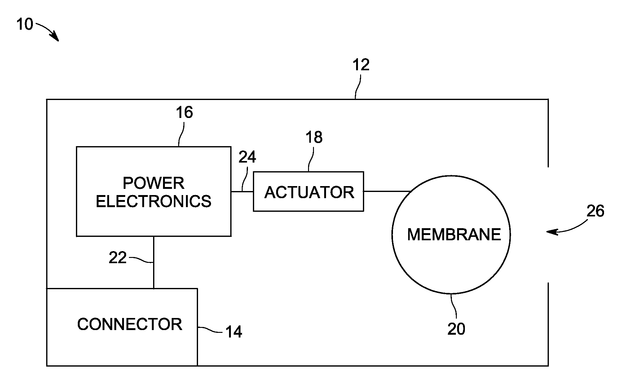
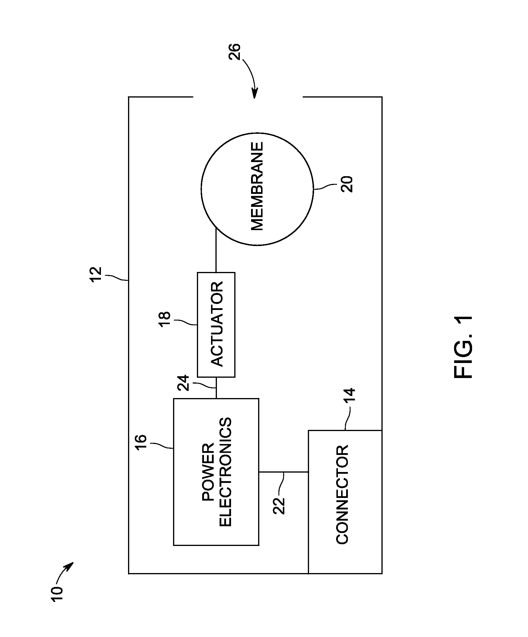
[0015]Turning to the figures, FIG. 1 is a block diagram of a synthetic jet device 10, in accordance with an embodiment of the invention. The synthetic jet device 10 includes a housing 12, connector 14, power electronics 16, actuator 18, and membrane 20....


PUM


Abstract

A synthetic jet device includes a housing, a connector within the housing configured to communicate with an exterior power source, driver electronics within the housing, a first membrane within the housing, and a second membrane within the housing.

Description

BACKGROUND OF THE INVENTION[0001]The subject matter disclosed herein relates to synthetic jets and more particularly to synthetic jet packaging.[0002]Microchips, LEDs, radio frequency components, memory chips, and other electronic devices may generate a significant amount of heat during use. These electronic devices should dissipate this energy in order to prevent damage and to extend their useful life. At times, the environment surrounding the electronic devices may be unable to provide the necessary cooling. In situations were the environment is unable to effectively cool, a cooling device may be included. The cooling device may therefore provide the necessary cooling in combination with the environment to extend the life and protect the electronic device. When including a cooling device to assist in heat removal, the cooling device itself may introduce a number of additional design challenges.BRIEF DESCRIPTION OF THE INVENTION[0003]In one embodiment, a cooling system includes a h...

Claims


Application Information

Patent Timeline
IPC IPC(8): H05K7/20H01L23/467
CPCF04B43/0027F04B43/046F04B45/047H01L23/4735H01L2224/48091H01L2924/00014B81B3/0018B81B3/0035H01L23/467H05K7/20B81B2201/03
Inventor ARIK, MEHMETPETROSKI, JAMESGURSOY, MUSTAFA
Owner GENERAL ELECTRIC CO
Learn More