
Devices and Methods for Reducing Electrical Noise in an Irrigated Electrophysiology Catheter System

a technology of irrigated electrophysiology and devices, which is applied in the field of devices and methods for reducing electrical noise in irrigated electrophysiology catheter systems, can solve problems such as the generation of electrical noise by peristaltic pumps, and achieve the effect of reducing noise signals

Inactive Publication Date: 2012-06-28
ST JUDE MEDICAL ATRIAL FIBRILLATION DIV
View PDF8 Cites 28 Cited by
  • Summary
  • Abstract
  • Description
  • Claims
  • Application Information

AI Technical Summary

Benefits of technology

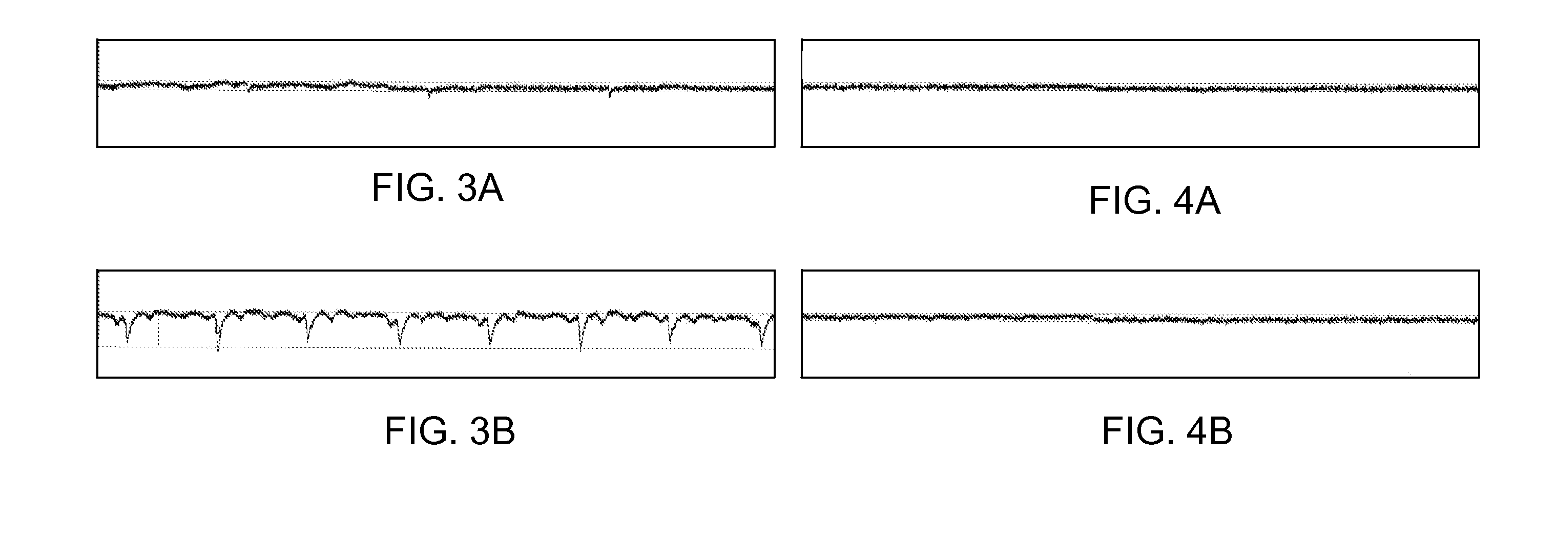
[0009]The inventors have discovered that the peristaltic pump noise signal is synchronized with the peristaltic pump rollers lifting away from the irrigation tubing. That is, the noise signal “spikes” when the irrigation fluid moves out of the peristaltic pump and into the irrigated electrophysiology catheter. The inventors have surprisingly discovered that, by minimizing surface adhesion between the irrigation tubing and the pump clamp, this noise signal can be minimized.
[0012]In another aspect, the present disclosure relates to a method of reducing noise in an irrigated electrophysiology catheter system. The irrigated electrophysiology catheter system includes a peristaltic pump including a pump clamp, a rotor, and an irrigation tube positioned between the pump clamp and the rotor. The method includes treating at least one of the pump clamp and the irrigation tube to reduce surface adhesion therebetween.
[0014]Advantageously, the present disclosure provides a peristaltic pump for use in connection with irrigated electrophysiology catheters that exhibits a reduced noise signal.

Problems solved by technology

It is known, however, that peristaltic pumps may generate electrical noise, which may undesirably couple to an electrogram signal measured by the electrodes on the irrigated electrophysiology catheter, to an electroanatomical visualization, localization and / or position system coupled to a subject, and / or to other diagnostic or therapeutic equipment.

Method used


Image

  • Devices and Methods for Reducing Electrical Noise in an Irrigated Electrophysiology Catheter System
  • Devices and Methods for Reducing Electrical Noise in an Irrigated Electrophysiology Catheter System
  • Devices and Methods for Reducing Electrical Noise in an Irrigated Electrophysiology Catheter System

Examples


Embodiment Construction

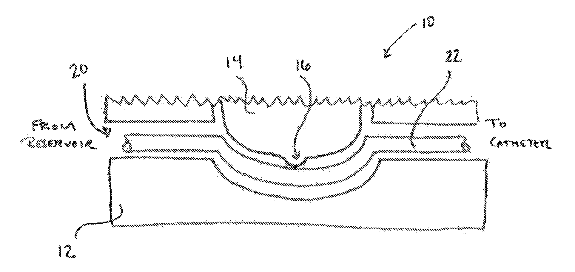
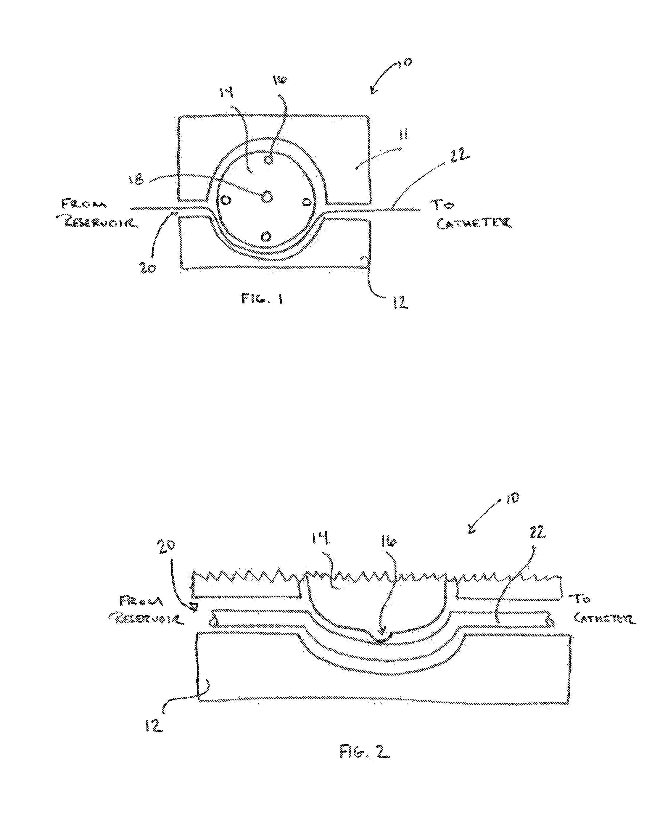
[0020]Referring now to the figures, and in particular to FIGS. 1 and 2, a peristaltic pump 10 is shown in schematic illustration. The configuration and operation of peristaltic pump 10 will be familiar to those of skill in the art, such that a detailed explanation thereof is not necessary herein. Instead, only those features of peristaltic pump 10 pertinent to understanding the present disclosure will be described below.

[0021]Peristaltic pump 10 generally includes a housing 11, a pump clamp 12, and a rotor 14. Rotor 14 includes a plurality of rollers 16 spaced about the circumference of rotor 14 and is mounted to rotate about an axle 18. Typically, although not necessarily, rollers 16 are evenly spaced about the circumference of rotor 14.

[0022]A tubing channel 20 is defined between pump clamp 12 and rotor 14. Tubing channel 20 accommodates an irrigation tube 22. One end of irrigation tube 22 can be coupled to a suitable reservoir of irrigation fluid (not shown), while the opposite e...


PUM


Abstract

An irrigation system for use with an irrigated electrophysiology catheter includes a peristaltic pump and an irrigation tube. The pump generally includes a pump clamp and a rotor, which are spaced apart to provide a tubing channel therebetween. The irrigation tube is inserted into the tubing channel. At least one of the pump clamp and the irrigation tube is treated to reduce surface adhesion therebetween. This advantageously minimizes perturbations to the double layer, which reduces a noise signal that might otherwise couple to and distort an electrogram signal.

Description

BACKGROUND OF THE INVENTION[0001]a. Field of the Invention[0002]The present disclosure relates to irrigated electrophysiology catheters. In particular, the present disclosure relates to devices and methods for reducing electrical noise in irrigated electrophysiology catheter systems.[0003]b. Background Art[0004]Catheters are used for an ever growing number of medical procedures. To name just a few examples, catheters are used for diagnostic, therapeutic, and ablative procedures. Typically, the physician manipulates the catheter through the patient's vasculature to the intended site, such as a site within the patient's heart. The catheter typically carries one or more electrodes (in the case of so-called “electrophysiology catheters”) or other diagnostic or therapeutic devices, which can be used for ablation, diagnosis, cardiac mapping, or the like.[0005]Irrigated electrophysiology catheters are also known. An irrigated electrophysiology catheter is an electrophysiology catheter that...

Claims


Application Information

Patent Timeline
IPC IPC(8): A61M1/00
CPCA61B18/1492A61B2217/007A61M3/0258
Inventor KEH, SANDRABEDNAREK, MICHAEL C.
Owner ST JUDE MEDICAL ATRIAL FIBRILLATION DIV
Learn More