
Method for Correcting Hyperstereoscopy and Associated Helmet Viewing System

a hyperstereoscopy and viewing system technology, applied in image enhancement, image analysis, instruments, etc., can solve the problems of hyperstereoscopy being perceived as troublesome by users, the size of the camera is too big, and the natural separation dip is difficult to comply with

Inactive Publication Date: 2012-06-28
THALES SA
View PDF3 Cites 5 Cited by
  • Summary
  • Abstract
  • Description
  • Claims
  • Application Information

AI Technical Summary

Benefits of technology

The invention is a method for correcting hyperstereoscopy in a helmet viewing device worn by a pilot. The method involves reconstructing the right and left images so as to obtain the picture shots equivalent to natural stereoscopy without having to position oneself at the natural physiological separation of 65 mm. The method uses a graphical calculator to process the images and includes steps such as decomposition of the images, calculation of associated distances, and reconstruction of the images. The helmet viewing device includes a first binocular assembly of image sensors, a second binocular helmet viewing assembly, and a graphical calculator for processing the images. The technical effect of the invention is to provide a more realistic and comfortable view for the pilot during flight operations.

Problems solved by technology

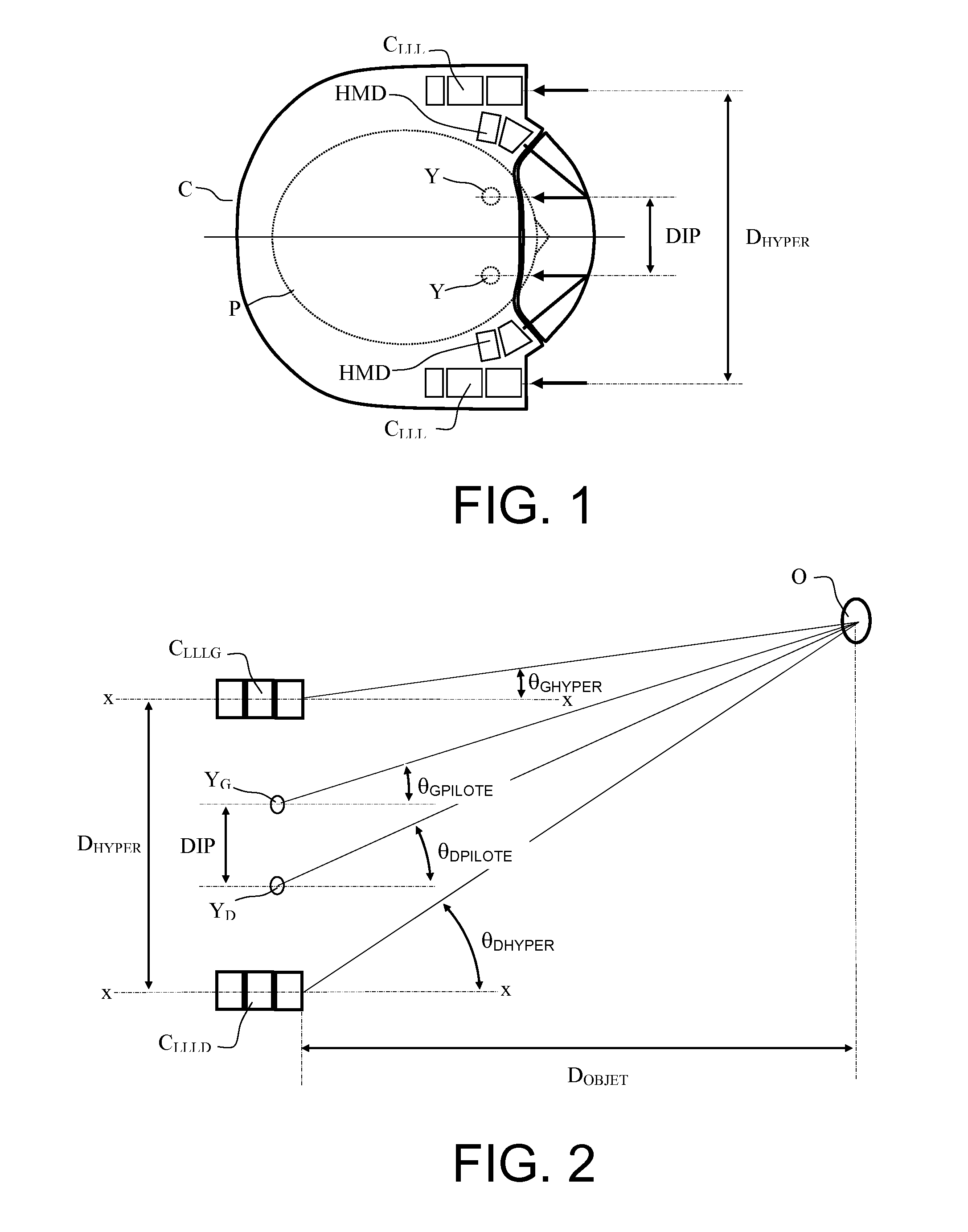
Certain constraints may lead to system architectures where the natural separation of the eyes is not complied with between the two cameras when, for example, the size of the cameras is too big.
In the case of a helmet viewing system such as represented in FIG. 1 where, as was stated, the sensors BNL are integrated into the helmet, the natural separation DIP is difficult to comply with if it is desired to culminate in optimal integration of the system in terms of simplicity of production, weight and volume.
Nonetheless, this hyperstereoscopy is perceived as troublesome by users.
This solution gives rise to excessive constraints for the integration of cameras or night sensors.
However, these processing operations are performed in non-real time, by post-processing and are too unwieldy to embed for real-time operation as demanded by helmet viewing systems.

Method used


Image

  • Method for Correcting Hyperstereoscopy and Associated Helmet Viewing System
  • Method for Correcting Hyperstereoscopy and Associated Helmet Viewing System
  • Method for Correcting Hyperstereoscopy and Associated Helmet Viewing System

Examples


Embodiment Construction

[0023]The aim of the method according to the invention consists in obtaining natural stereoscopic vision on the basis of a binocular picture-capture system which is hyperstereoscopic by construction. This requires that the left and right images be recalculated on the basis of an analysis of the various elements making up the scene and of the evaluation of their distances. This also requires precise knowledge of the models of the system of sensors so as to facilitate the search for the elements and their registration.

[0024]The method for correcting hyperstereoscopy according to the invention therefore rests on two principles. On the one hand, it is possible to determine particular elements in an image and to displace them within this image and on the other hand, by virtue of the binocularity of the viewing system, it is possible to determine the distance separating the real elements from the viewing system.

[0025]More precisely, the method comprises the following four steps: Step 1: D...


PUM


Abstract

The general field of the invention relates to binocular helmet viewing devices worn by aircraft pilots. In night use, one of the drawbacks of this type of device is that the significant distance separating the two sensors introduces hyperstereoscopy on the images restored to the pilot. The method according to the invention is a scheme for removing this hyperstereoscopy in the images presented to the pilot by graphical processing of the binocular images. Comparison of the two images makes it possible to determine the various elements present in the image, to deduce therefrom their distances from the aircraft and then to displace them in the image so as to restore images without hyperstereoscopic effects.

Description

CROSS-REFERENCE TO RELATED APPLICATION[0001]This application claims priority to foreign French patent application No. FR 1005074, filed on Dec. 23, 2010, the disclosure of which is incorporated by reference in its entirety.FIELD OF THE INVENTION[0002]The field of the invention is that of helmet viewers comprising low light level viewing devices used in aircraft cockpits. The invention applies most particularly to helicopters used for night missions.BACKGROUND[0003]A night viewing system necessarily comprises low light level sensors or cameras and a helmet display worn by the pilot on his head which displays, superimposed on the exterior landscape, the images arising from these sensors. These systems are generally binocular so as to afford the maximum of visual comfort. In a certain number of applications, the low light level sensors are integrated into the helmet, thereby considerably simplifying the system while best reducing the parallax effects introduced by the difference in pos...

Claims


Application Information

Patent Timeline
Patent Type & Authority Applications(United States)
IPC IPC(8): G02B27/01
CPCG06T5/50G06T2207/30212H04N13/128H04N13/156H04N13/344
Inventor FRANCOIS, JEAN-MICHELELLERO, SÉBASTIENGROSSETETE, MATTHIEUBAUDOU, JOËL
Owner THALES SA
Learn More