
Beamforming array antenna control system and method for beamforming using the same

a control system and array antenna technology, applied in the direction of antennas, electrical equipment, etc., can solve the problems of complex structure, inconvenient communication through precise beamforming of typical beamforming networks, and difficulty in realizing typical beamforming networks at high frequency, so as to shorten search time

Active Publication Date: 2012-06-28
KOREA ELECTRONICS TECH INST
View PDF0 Cites 23 Cited by
  • Summary
  • Abstract
  • Description
  • Claims
  • Application Information

AI Technical Summary

Benefits of technology

[0009]The present invention has been made in an effort to provide a beamforming array antenna control system and a method for beamforming using the same having advantages of shortening a search time.
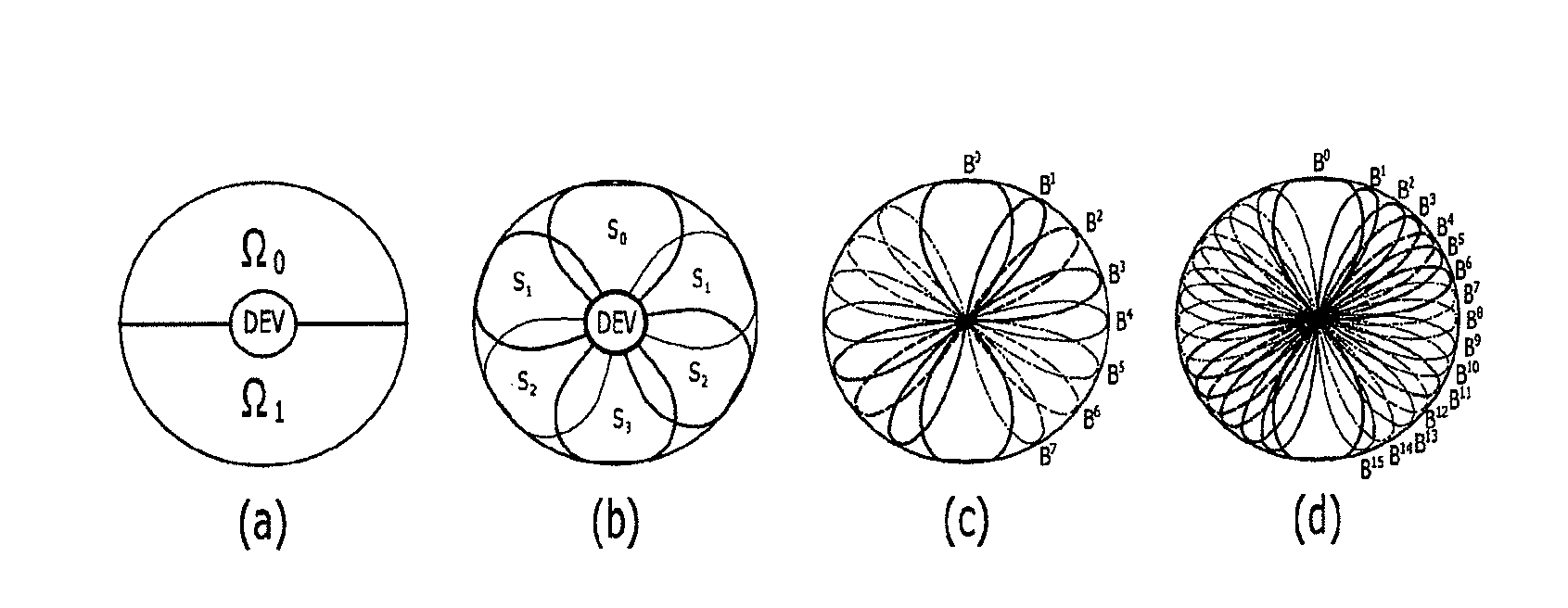
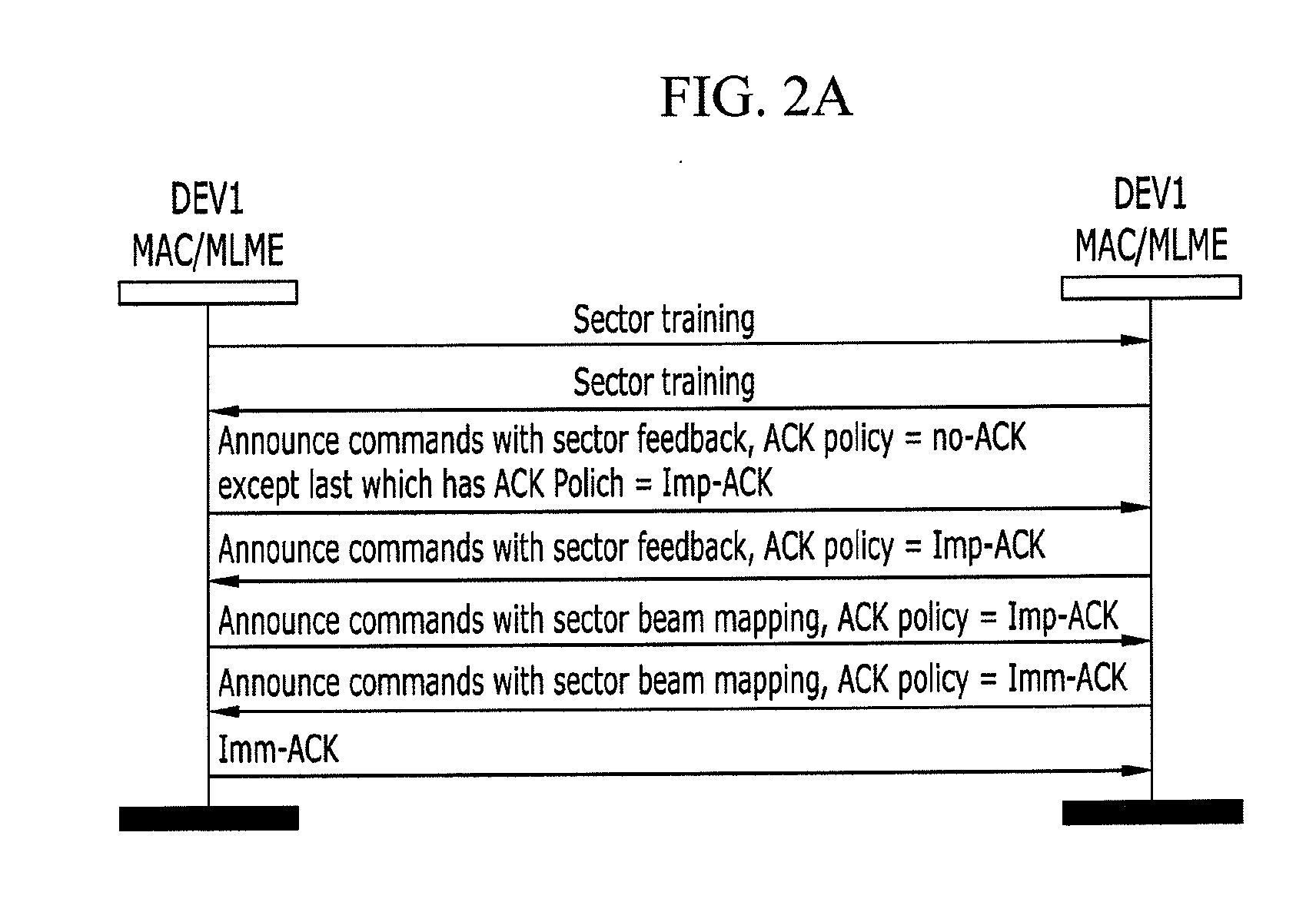
[0014]According to an exemplary embodiment of the present invention, a beam protocol is satisfied because beamforming communication is performed by controlling the number of arrays of antenna, and a search time is shorted by quickly and precisely searching for a target.

Problems solved by technology

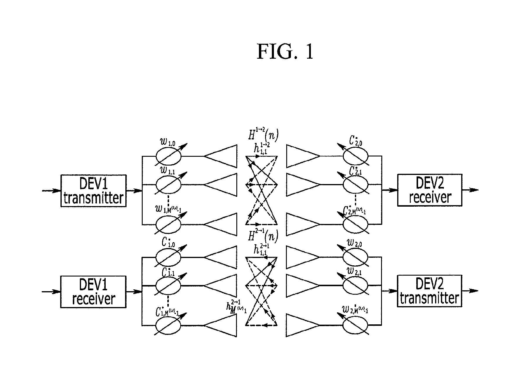
Such a typical beamforming network structure can control an output beam direction but have a complicated structure.
Accordingly, it is difficult to realize the typical beamforming network at high frequency.
Furthermore, since a comparatively long time is required in beamforming communication and a beam angle cannot be controlled in the typical beamforming network, the typical beamforming network is not proper for communication through precise beamforming.

Method used


Image

  • Beamforming array antenna control system and method for beamforming using the same
  • Beamforming array antenna control system and method for beamforming using the same
  • Beamforming array antenna control system and method for beamforming using the same

Examples


Embodiment Construction

[0021]In the following detailed description, only certain exemplary embodiments of the present invention have been shown and described, simply by way of illustration. As those skilled in the art would realize, the described embodiments may be modified in various different ways, all without departing from the spirit or scope of the present invention. Accordingly, the drawings and description are to be regarded as illustrative in nature and not restrictive. Like reference numerals designate like elements throughout the specification.

[0022]Through the specification, unless explicitly described to the contrary, the word “comprise” and variations such as “comprises” or “comprising”, will be understood to imply the inclusion of stated elements but not the exclusion of any other elements.

[0023]Hereinafter, a beamforming array antenna and a beamforming method using the same will be described with reference to the accompanying drawing. Prior to describing an exemplary embodiment of the prese...


PUM


Abstract

A control system connected to a plurality of array antenna performs beamforming. In order to perform the beamforming, the control system receives response beams inputting to a first antenna group predetermined from a plurality of array antenna in response to radiate beams and decides a sector having comparatively stronger intensity. And the control system receives response beams inputting to a second antenna group, decides a plurality of beam levels and decides a final beam pair among the plurality of the decided beam levels.

Description

CROSS-REFERENCE TO RELATED APPLICATION[0001]This application claims priority to and the benefit of Korean Patent Application No. 10-2010-0134875 filed in the Korean Intellectual Property Office on Dec. 24, 2010, the entire contents of which are incorporated herein by reference.BACKGROUND OF THE INVENTION[0002](a) Field of the Invention[0003]The present invention relates a beamforming array antenna control system and a method for beamforming using the same.[0004](b) Description of the Related Art[0005]Lately, various near field communication technologies have been actively developed. Among them, a near field communication using a 60 GHz band has been receiving greater attention due to advantages of a 60 GHz band. Although 60 GHz band has great atmospheric attenuation, 60 GHz band has a high frequency reuse factor and a high collimation factor. A related communication protocol for a high speed data transmission, for example, about 1 Gbps or faster, has been defined in order to high sp...

Claims


Application Information

Patent Timeline
Patent Type & Authority Applications(United States)
IPC IPC(8): H01Q3/00
CPCH01Q25/00H01Q3/00
Inventor KIM, KI JINAHN, KWANG HOPARK, SANGHOONYU, JONG-WONTAE, HYUN SUNG
Owner KOREA ELECTRONICS TECH INST
Learn More