
Electric receptacle apparatus with replaceable protection module

a protection module and electric receptacle technology, applied in the direction of coupling device connection, fire alarm, instruments, etc., can solve the problems of surge absorber being disabled or on fire, surge absorber being operated in an excessive temperature or damage, surge absorber capacity finite or finite lifetime, etc., to achieve more safe protection

Active Publication Date: 2012-06-28
POWERTECH INDAL
View PDF7 Cites 46 Cited by
  • Summary
  • Abstract
  • Description
  • Claims
  • Application Information

AI Technical Summary

Benefits of technology

"The present patent describes an electric receptacle apparatus with a receptacle module and a protection module that can be easily replaced by the user. The protection module includes a casing, a switch unit, a protection circuit, and conductive terminals that are connected with the power output interface. The conductive terminals are plugged in the conductive jacks when the protection module is recessed in the receptacle module. The protection circuit is installed in the casing for protecting the electrical device plugged in the power output interface. The switch unit is connected with the protection circuit and the conductive terminals. The electric receptacle apparatus provides a convenient way to replace the protection module in case of failure, ensuring safer protection for the electric receptacle apparatus."

Problems solved by technology

As a result, the surge will make the switch unit be operated in an excessive temperature or damage an electronic product plugged in the electric receptacle apparatus.
The excessive temperature may cause the surge absorber to be disabled or be on fire.
Therefore, the capacity of the surge absorber is finite or the lifetime of the surge absorber is finite.
In general, the user may throw away the whole electric receptacle apparatus when the surge absorber has damaged.
That will increase the economic cost of the electric receptacle apparatus and reduce the use efficiency of the electric receptacle apparatus.
It is inconvenient for the user and the damage condition of the switch unit may be ignored.

Method used


Image

  • Electric receptacle apparatus with replaceable protection module
  • Electric receptacle apparatus with replaceable protection module
  • Electric receptacle apparatus with replaceable protection module

Examples


Embodiment Construction

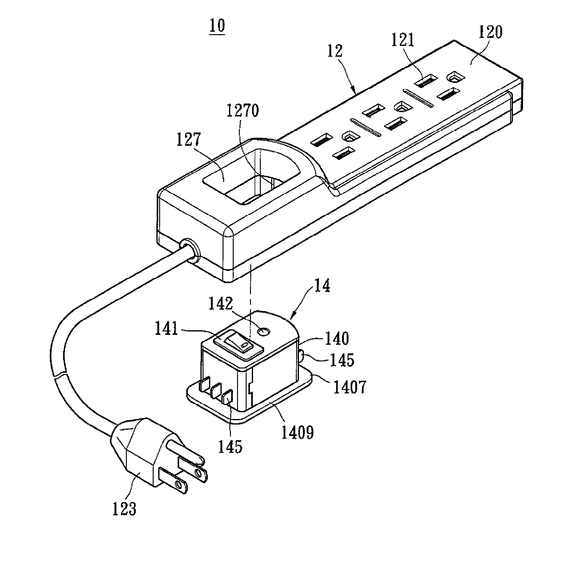
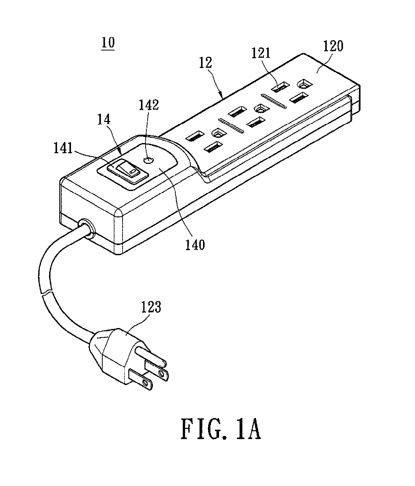
[0027]Refer to FIG. 1A. FIG. 1A illustrates a schematic diagram of an electric receptacle apparatus according to a first exemplary embodiment of the present disclosure. The electric receptacle apparatus with replaceable protection module 10 comprises a receptacle module 12 and a protection module 14. FIG. 1A illustrates the protection module 14 is recessed in the receptacle module 12.

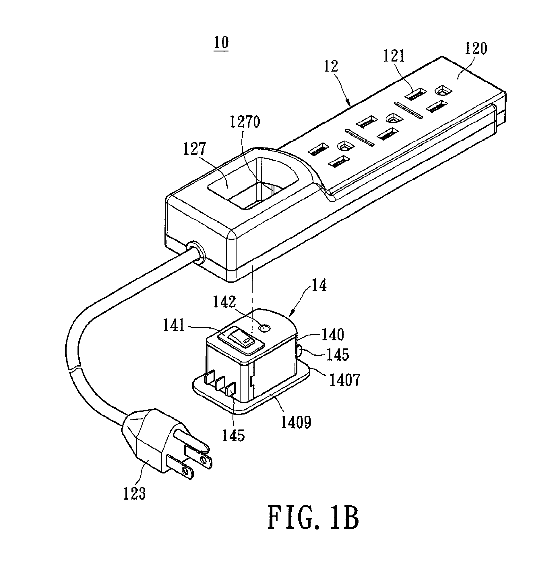
[0028]Please refer to FIG. 1A and associated with FIG. 1B. FIG. 1B illustrates another schematic diagram of the electric receptacle apparatus according to the first exemplary embodiment of the present disclosure. In one complementation, the protection module 14 is connected with or separated from the receptacle module 12 alternatively.

[0029]The receptacle module 12 includes a body 120, a power output interface 121, power input interface 123 and an accommodation portion 127. The protection module 14 has a casing 140, a switch unit 141, a plurality of conductive terminals 145 and an indicating unit 142. T...


PUM


Abstract

An electric receptacle apparatus with a replaceable protection module is disclosed. The electric receptacle apparatus includes a receptacle module and a protection module. The receptacle module has a body, am accommodation portion, a power input interface and a power output interface. The accommodation portion is installed inside the body and has a plurality of conductive jacks, wherein the conductive jacks are electrically connected with power input interface and the power output interface respectively. The protection module has a casing, a switch unit, a protection circuit and a plurality of conductive terminals, wherein the switch unit connects with protection circuit and the conductive terminals. Whereby, when the protection module is recessed in the accommodation portion, the conductive terminals are plugged in the conductive jacks and the switch unit controls the power input interface to be electrically connected with or electrically disconnected from the power output.

Description

BACKGROUND OF THE INVENTION[0001]1. Field of the Invention[0002]The present disclosure relates to an electric receptacle apparatus, especially to an electric receptacle apparatus with a protection module.[0003]2. Description of Related Art[0004]A conventional electric receptacle apparatus integrated a switch unit has a key or a press-button disposed on the electric receptacle apparatus for receiving an outside manual operation from a user. The switch unit is configured to control an output port of the electrical receptacle apparatus to start to output a power or stopping outputting the power from an input port. The electric receptacle apparatus may receive an unusual peak voltage such as a surge from the input port when the switch unit is changed the operation state every time. As a result, the surge will make the switch unit be operated in an excessive temperature or damage an electronic product plugged in the electric receptacle apparatus.[0005]One conventional solving method is u...

Claims


Application Information

Patent Timeline
Patent Type & Authority Applications(United States)
IPC IPC(8): G08B17/00H02H9/04H02H3/20
CPCH01H9/0271H01H9/08H01H37/46H01H37/74H02H9/042H01R13/514H01R13/6666H01R13/70H01R25/003H01H2223/028
Inventor HSU, JUNG-HUI
Owner POWERTECH INDAL
Learn More