Switch Device
a technology of a switch and a contact chamber, which is applied in the direction of contacts, contact surface shape/structure, electrical equipment, etc., can solve the problems of imperfect contact of these contacts, contact chamber may possibly suck foreign materials, etc., and achieve the effect of reducing the contact due to foreign materials
- Summary
- Abstract
- Description
- Claims
- Application Information
AI Technical Summary
Benefits of technology
Problems solved by technology
Method used
Image
Examples
first exemplary embodiment
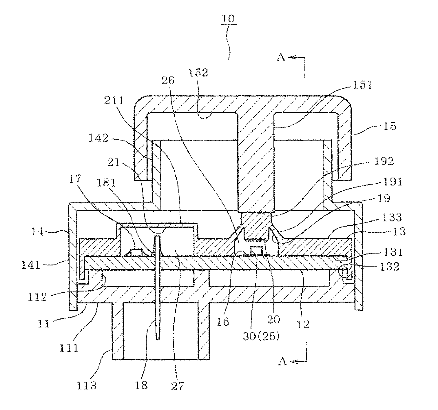
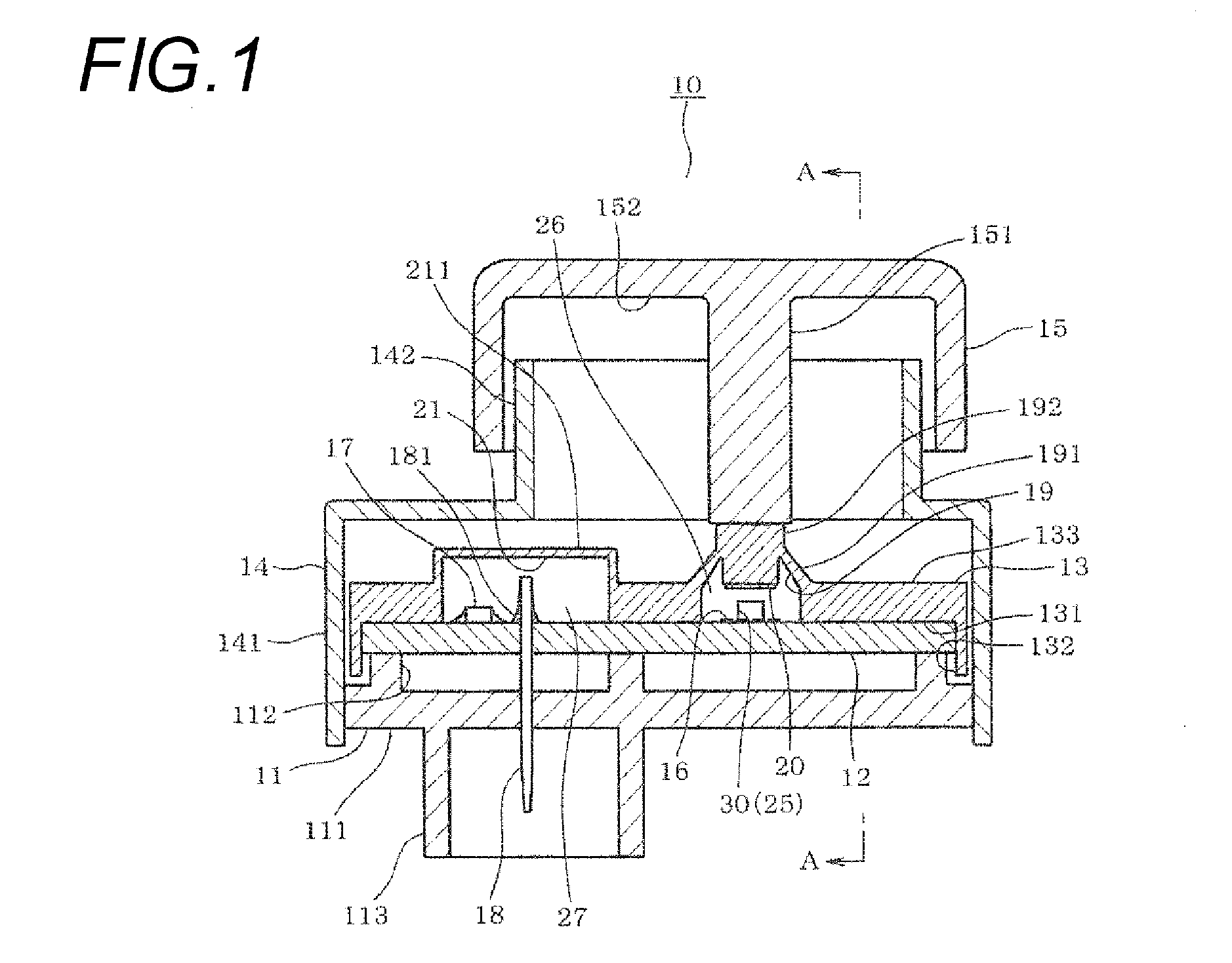
[0035]FIG. 1 shows a switch device 10 which is provided in, for instance, a vehicle to operate a turning on or off state of a defogger. An upper side of FIG. 1 will be described as an upper part of the switch device 10 and a lower side of FIG. 1 will be described as a lower part of the switch device 10, hereinafter.
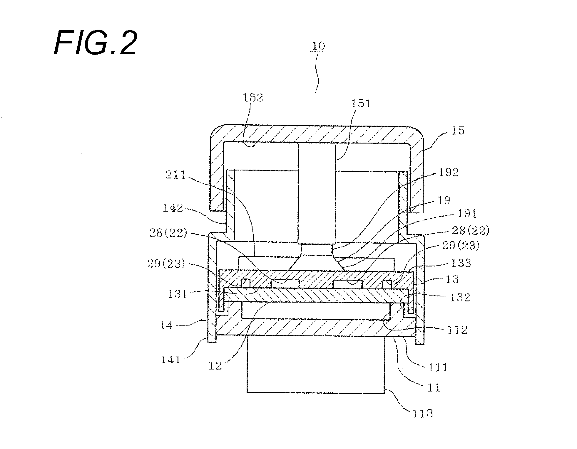
[0036]As shown in FIG. 1, FIG. 2 and FIG. 5, the switch device 10 includes a base 11, a base board 12, a rubber sheet 13, a case 14 and an operating member 15. The base 11 includes a main body part 111, a support part 112 and a connector part 113. The main body part 111 is formed in the shape of a rectangular plate. The support part 112 is provided in one surface of the main body part 111, namely, an upper side surface and formed in the shape of a rectangular box opened upward. The connector part 113 is provided in the other surface of the main body part 111, namely, a lower side surface opposite to the support part 112 and formed in the shape of a rectangular box opened ...
second exemplary embodiment
[0068]As shown in FIG. 6, a second exemplary embodiment is different from the first exemplary embodiment in view of a point that second recessed parts 31 are generally formed in circular shapes, namely, semicircular shapes. In this case, guide walls 311 of the second recessed parts 31 are formed in the shapes of circular arcs and connected to nonreturn parts 24. According to this structure, as shown by arrow marks C, foreign materials entering foreign accumulating chambers 28 advance along the guide walls 311 and are stopped by the nonreturn parts 24. Accordingly, the backflow of the foreign materials can be more effectively prevented.
third exemplary embodiment
[0069]As shown in FIG. 7, a third exemplary embodiment is different from the exemplary embodiments respectively in view of a point that second recessed parts 31 are generally formed in circular shapes, namely, semicircular shapes and nonreturn parts 32 are formed in the shapes of hooks bent inside the second recessed parts 31. According to this structure, foreign materials entering foreign material accumulating chambers 28 advance along guide walls 311, turn inside the nonreturn parts 32 and are stopped by the nonreturn parts 32 as shown by arrow marks D. Accordingly, the backflow of the foreign materials can be more effectively prevented.
[0070]In the above-described exemplary embodiments respectively, the rubber sheet 13 includes the two second recessed parts 22 or the two second recessed parts 31, the two guide grooves 23, the two nonreturn parts 24 or the two nonreturn parts 32 and the two vent grooves 25 relative to the one contact dome part 19. However, the present invention is...
PUM
 Abstract
Description
Claims
Application Information
 - R&D
- Intellectual Property
- Life Sciences
- Materials
- Tech Scout
- Unparalleled Data Quality
- Higher Quality Content
- 60% Fewer Hallucinations
Browse by: Latest US Patents, China's latest patents, Technical Efficacy Thesaurus, Application Domain, Technology Topic, Popular Technical Reports.
© 2025 PatSnap. All rights reserved.Legal|Privacy policy|Modern Slavery Act Transparency Statement|Sitemap|About US| Contact US: help@patsnap.com


