Eureka AIR delivers breakthrough ideas for toughest innovation challenges, trusted by R&D personnel around the world.

Power Input Efficiency Measurement Method

a technology of power input and measurement method, applied in the direction of power supply testing, instruments, computing, etc., can solve the problems of failing to disclose an improved method of measuring power efficiency, etc., to simplify the entire measurement procedure and power output efficiency

Inactive Publication Date: 2012-06-21
INFINNO TECH CORP
View PDF7 Cites 2 Cited by
  • Summary
  • Abstract
  • Description
  • Claims
  • Application Information

AI Technical Summary

Benefits of technology

"The present invention provides a power input efficiency measurement method that simplifies the entire measurement procedure. The method involves measuring the current and voltage at the primary side of a power converter using a current transformer and a negative-voltage conversion circuit, respectively. The power output efficiency can then be calculated by calculating the primary-side current and voltage. This method can be applied to different types of power converters, such as flyback converters and power electronic simulations. The technical effect of this invention is to provide a more efficient and accurate measure of power input efficiency."

Problems solved by technology

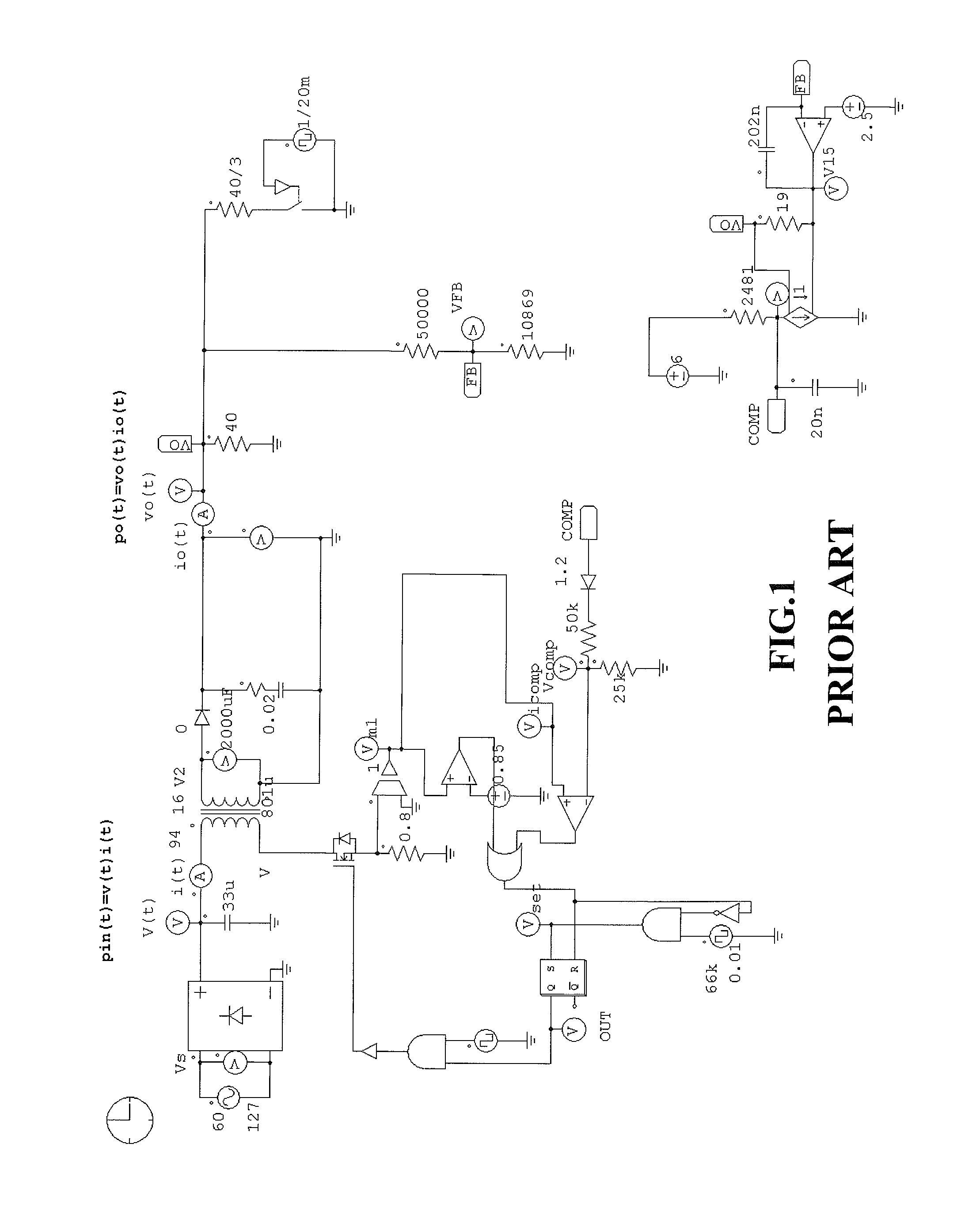
Yet further, with respect to the design of the flyback converter, it is not necessitated to provide a performance of electrical isolation with equipped electrical appliances.
However, it fails to disclose an improved method of measuring power efficiency.
However, it also fails to disclose an improved method of measuring power efficiency.

Method used


Image

  • Power Input Efficiency Measurement Method
  • Power Input Efficiency Measurement Method
  • Power Input Efficiency Measurement Method

Examples


Embodiment Construction

[0039]It is noted that a power input efficiency measurement method in accordance with the preferred embodiment of the present invention is suitable for measuring and calculating power efficiency η of power supplies applied in various power input systems or the likes which are not limitative of the present invention.

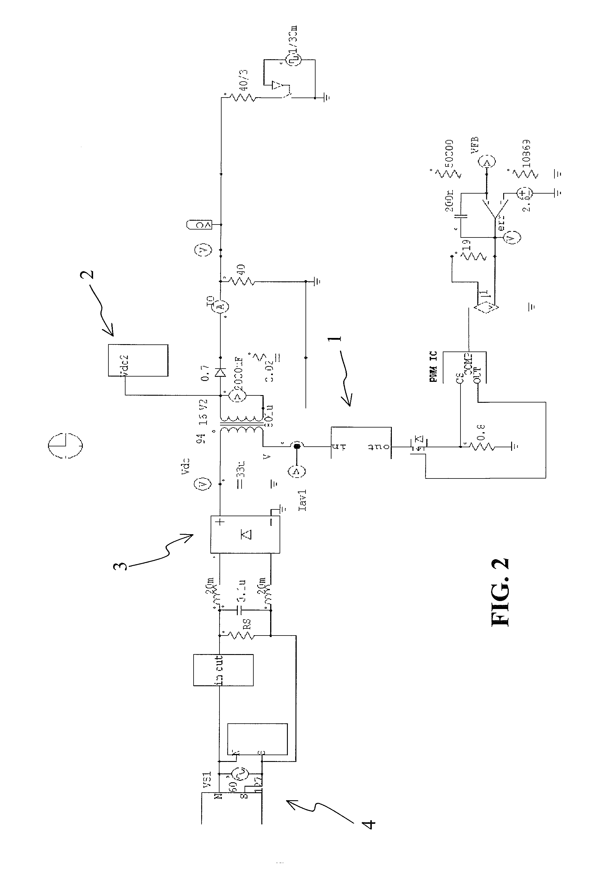
[0040]FIG. 2 shows a schematic diagram of a simulation circuit operated by a power input efficiency measurement method in accordance with a preferred embodiment of the present invention. Referring to FIG. 2, the power input efficiency measurement method of the present invention includes the step of: providing a power supply to a power input system which has a power converter or other power electronic converters (e.g. flyback converter). By way of example, a proper power source (e.g. utility power) supplies power to the power input system. In a preferred embodiment, a power electronic simulation procedure is applied to simulate a power output. For example, the power electr...


PUM


Abstract

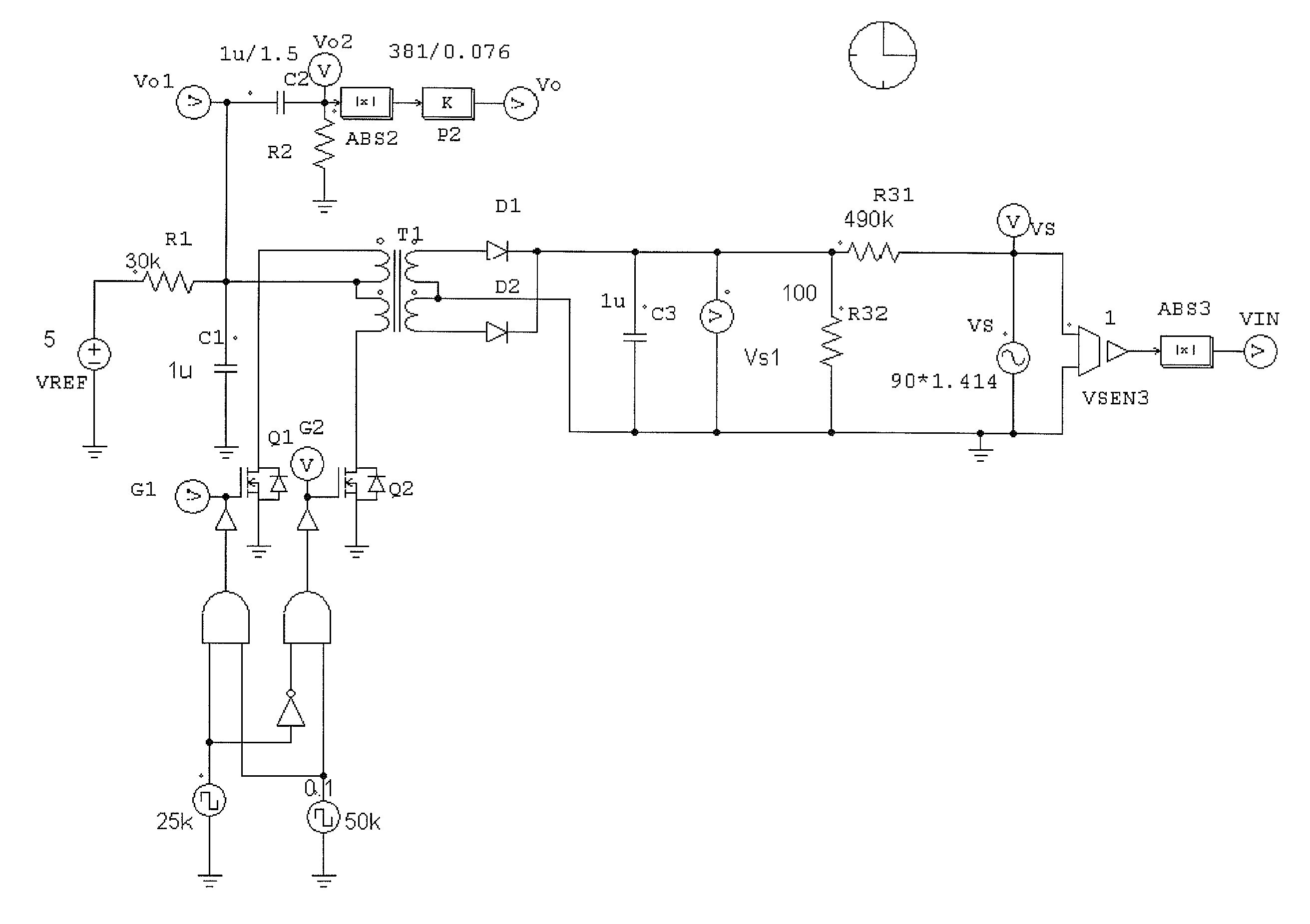
A power input efficiency measurement method includes: providing a power source to supply to a power input system that has a power converter; measuring a current at a primary side of the power converter; measuring a voltage at the primary side of the power converter; and calculating the primary-side current and the primary-side voltage to obtain power efficiency of the power input system. In a preferred embodiment, a current transformer unit is applied to measure the primary-side current while a negative-voltage conversion circuit is applied to measure the primary-side voltage.

Description

BACKGROUND OF THE INVENTION[0001]1. Field of the Invention[0002]The present invention relates to a power input efficiency measurement method. More particularly, the present invention relates to the power input efficiency measurement method for measuring a systematic efficiency of a power supply.[0003]2. Description of the Related Art[0004]In general, flyback converters have a circuitry structure of a buck-boost converter which provides a characteristic of electrical isolation. The circuitry structure of the flyback converter has several advantages of low cost, well developed technique and simpler structures. Furthermore, the flyback converter can also achieve multiple output purposes so that it will be widely used in auxiliary power supply design for supplying auxiliary power to the whole system. Yet further, with respect to the design of the flyback converter, it is not necessitated to provide a performance of electrical isolation with equipped electrical appliances.[0005]Although ...

Claims


Application Information

Patent Timeline
Patent Type & Authority Applications(United States)
IPC IPC(8): G06F19/00G01R19/00
CPCG01R31/42G01R21/06
Inventor CHUNG, CHIH-HSIANGCHANG, FENG-JENCHIANG, HSUANG-CHANG
Owner INFINNO TECH CORP
Why Eureka
Eureka Blog
Learn More