
Switching Parameter Based Discontinuous Mode-Critical Conduction Mode Transition

a technology of switching parameter and transition mode, applied in the field of electrical equipment, can solve problems such as low efficiency

Active Publication Date: 2012-06-21
SIGNIFY HLDG BV
View PDF3 Cites 32 Cited by
  • Summary
  • Abstract
  • Description
  • Claims
  • Application Information

AI Technical Summary

Benefits of technology

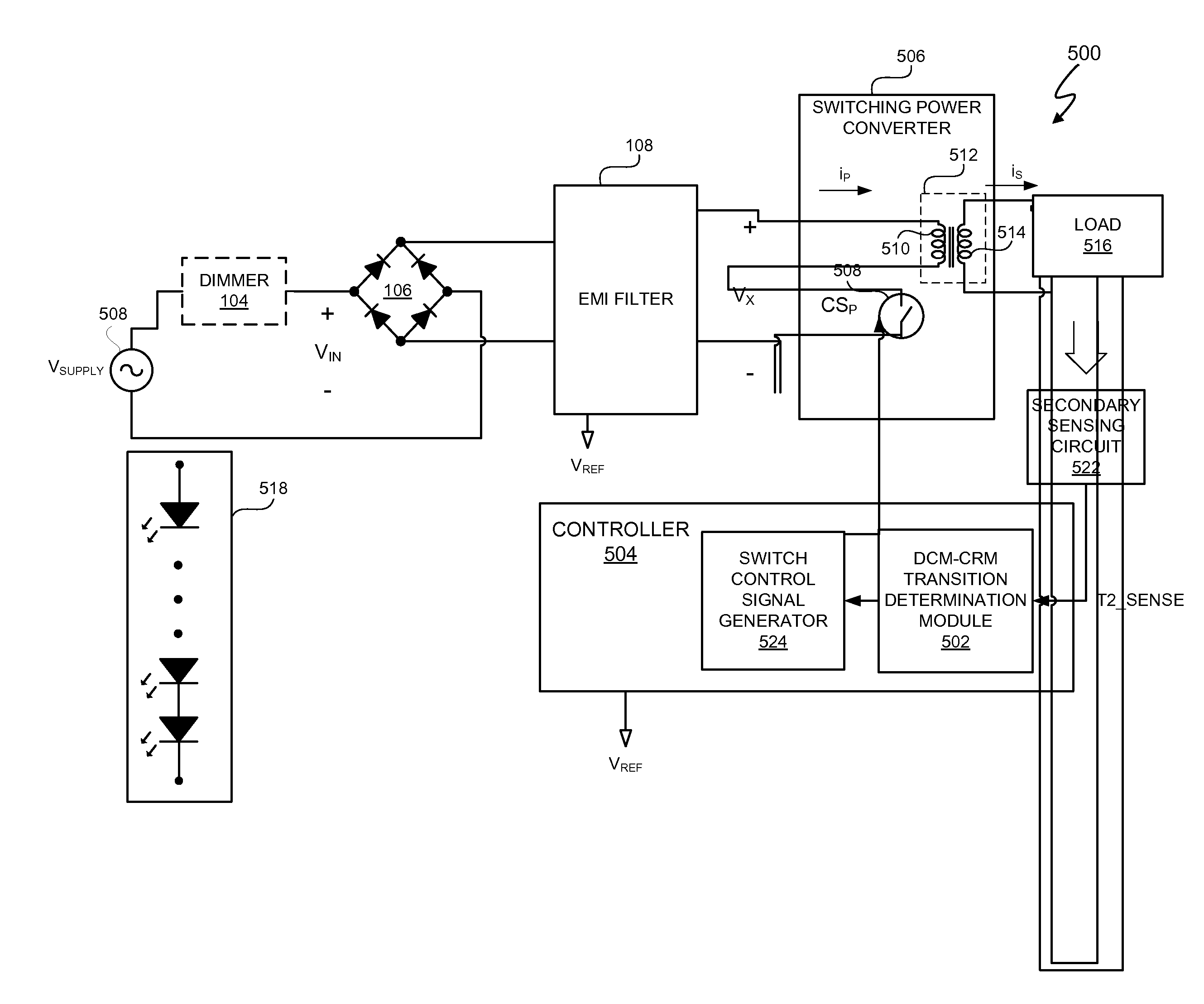
[0017]In a further embodiment of the present invention, an apparatus includes a switching power converter. The apparatus further includes a controller, coupled to the switching power converter, to provide at least dual-mode conduction control of the switching power converter. The controller is capable of controlling transitions between discontinuous conduction mode and critical conduction mode of the switching power converter using a measured switching time parameter having a value corresponding with an approximately peak voltage of a time-varying supply voltage supplied to the switching power converter. The controller is further capable of controlling power factor correction for the switching power converter. The apparatus also includes a load coupled to the switching power converter.

Problems solved by technology

Higher switching frequencies can correspond to higher switching losses and, thus, lower efficiency.

Method used


Image

  • Switching Parameter Based Discontinuous Mode-Critical Conduction Mode Transition
  • Switching Parameter Based Discontinuous Mode-Critical Conduction Mode Transition
  • Switching Parameter Based Discontinuous Mode-Critical Conduction Mode Transition

Examples


Embodiment Construction

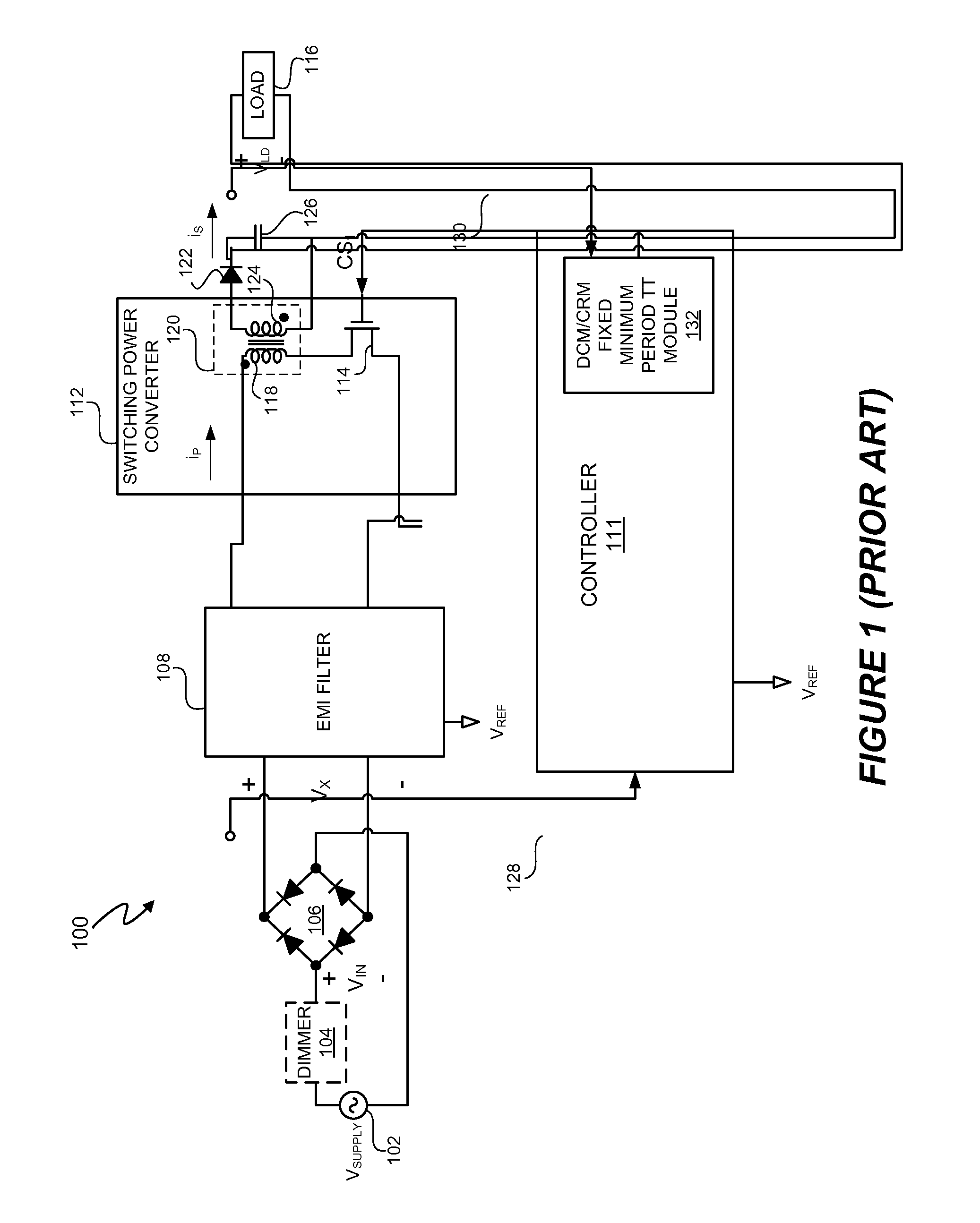
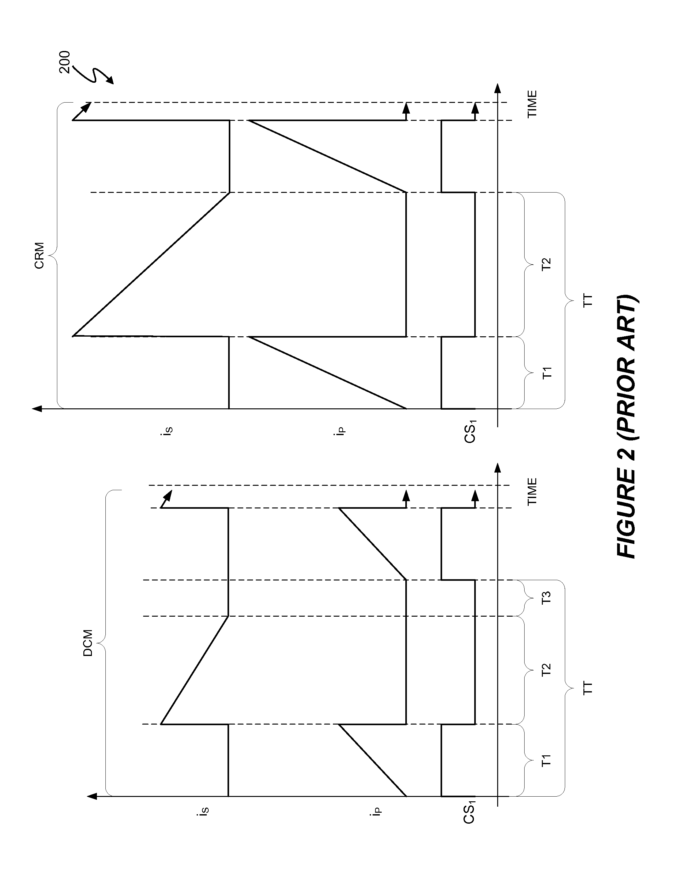
[0031]In at least one embodiment, an electronic system includes a controller to provide at least dual-mode conduction control of a switching power converter. “At least dual-mode conduction control” means, in at least one embodiment, providing control for at least two modes of conduction such as two or more of discontinuous conduction mode (DCM), critical conduction mode (CRM), and continuous conduction mode (CCM). In at least one embodiment, the controller is capable to control transitions between DCM and CRM of the switching power converter using a measured switching time parameter having a value corresponding with an approximately peak voltage of a time-varying supply voltage supplied to the switching power converter. In at least one embodiment, the switching power converter includes a transformer that includes a primary side coil and a secondary side coil. The transformer transfers energy to a load. In at least one embodiment, the measured switching time parameter value used by t...


PUM


Abstract

An electronic system includes a controller to provide at least dual-mode conduction control of a switching power converter. In at least one embodiment, the controller is capable to control transitions between discontinuous conduction mode (DCM) and critical conduction mode (CRM) of the switching power converter using a measured switching time parameter having a value corresponding with an approximately peak voltage of a time-varying supply voltage supplied to the switching power converter. In at least one embodiment, the controller dynamically compensates for changing parameters of the electronic system by dynamically determining a minimum non-conductive time of the control switch of the switching power converter using the measured switching time parameter value at approximately the peak of the supply voltage of the supply voltage.

Description

CROSS-REFERENCE TO RELATED APPLICATION[0001]This application claims the benefit under 35 U.S.C. §119(e) and 37 C.F.R. §1.78 of U.S. Provisional Application No. 61 / 423,883, filed on Dec. 16, 2010, and is incorporated by reference in its entirety.BACKGROUND OF THE INVENTION[0002]1. Field of the Invention[0003]The present invention relates in general to the field of electronics, and more specifically to a method and system for determining and utilizing a switching parameter of a switching power converter to facilitate transitions between discontinuous conduction mode and critical conduction mode.[0004]2. Description of the Related Art[0005]Many electronic systems include circuits, such as switching power converters to provide efficient power conversion from a voltage supply into a regulated output voltage. When converting an alternating current (“AC”) supply voltage into a regulated output voltage, switching power converters utilize a switch that turns ON and OFF multiple times during ...

Claims


Application Information

Patent Timeline
IPC IPC(8): H05B41/282H05B37/02H02M3/335H02M1/00H05B44/00
CPCH02M3/33523H02M2001/0003Y02B20/346H05B33/0815H02M2001/007Y02B20/30H05B45/3725H05B45/385H02M1/0003H02M1/007H02M3/33507
Inventor MELANSON, JOHN L.HE, ZHAOHUI
Owner SIGNIFY HLDG BV
Learn More