
Conformal cannula device and related methods

a cannula and cannula technology, applied in the field of connectors, can solve the problems of various difficulties in connecting a conduit assembly with the heart, and achieve the effect of sufficient stiffness

Inactive Publication Date: 2012-06-07
WORLD HEART +1
View PDF14 Cites 61 Cited by
  • Summary
  • Abstract
  • Description
  • Claims
  • Application Information

AI Technical Summary

Benefits of technology

[0007]In accordance with another embodiment, another cannula assembly is provided that comprises a tubular structure coupled with a conformal flange. The conformal flange assembly is configured to exhibit a first, collapsed state and a second, expanded state wherein the conformal flange extends substantially radially outward relative to the tubular structure. A proximal surface of the conformal flange is formed of a material that promotes tissue in-growth.
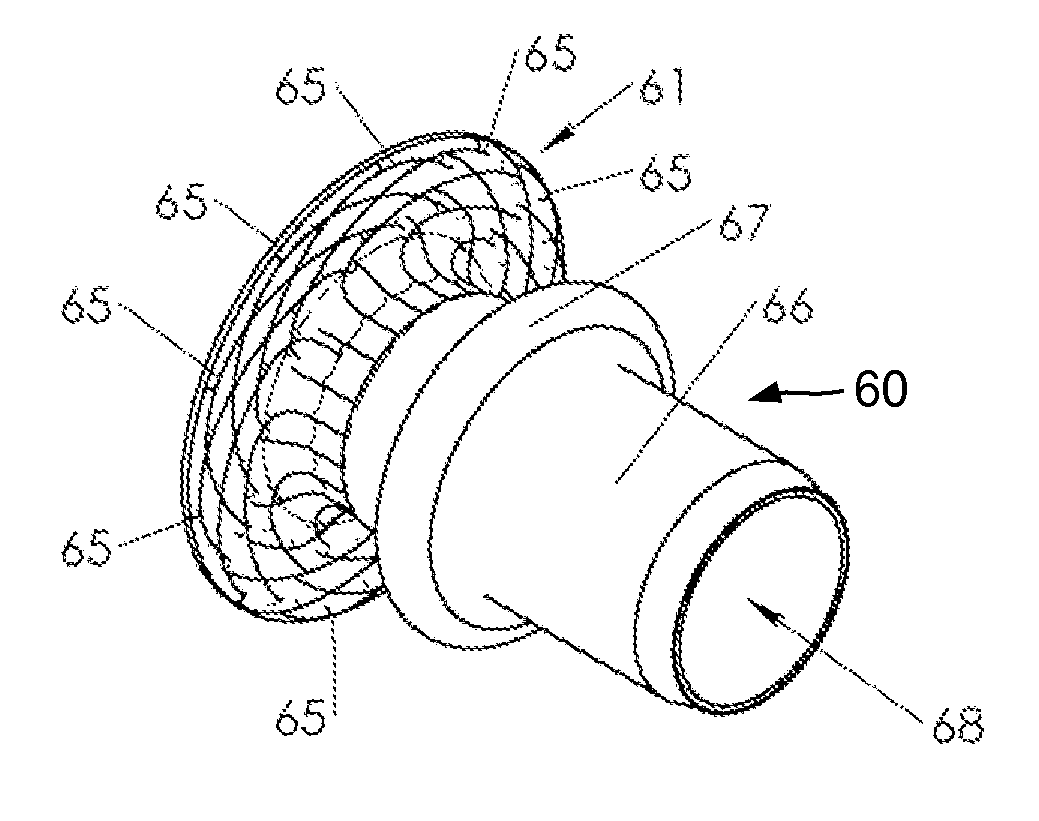
[0009]In accordance with another embodiment of the present invention, a cannula is provided for the transport of blood. The cannula comprises an elongate, flexible tubular conduit defining a blood channel therethrough between a first end and a second end. The conduit is flexible but exhibits a sufficient stiffness to avoid kinking or collapse due to suction forces that may be applied thereto. The first end comprises an adaptor for connection to a heart and a second end is configured for connection to a device such as a blood pump. In one embodiment, the adaptor is resiliently-flexible and assumes an expanded configuration having a wide inlet mouth while in an expanded or deployed configuration. The adaptor is configured to be inserted through incision or other opening within the heart by introduction while in a collapsed or contracted state. Once introduced into, for example, a ventricle of the heart, the adaptor (which may be self expanding) is deployed to assume a desired configuration as a juncture to the heart. In one embodiment, the inflow adaptor assumes a saucer-shaped mouth geometry and is a composite structure comprising a framework of elastic wireforms and a material displaced along the enclosed area wire framework to provide a substantially leak proof conduit.
[0010]In an embodiment, there is provided a method to deploy the cannula inlet adaptor in a collapsed or compressed condition and then to expand the prosthesis when it has been moved from the remote location to the location to be installed. In one embodiment, the prosthesis, when deployed, radially exceeds the diameter of the fenestra created within the ventricular wall. According to the present invention, the prosthesis is self-expanding once introduced and deployed. Such a prosthesis is compressed within a constraint provided by an introducer. Once in position, the constraint is removed when the introducer is actuated to disengage the prosthesis and allows the inlet adaptor to resiliently self-expand into a “wide mouth configuration”. In the expanded configuration, the inflow adaptor is preferably in contact with the interior surface (endocardium) of the heart and allows some flex as the heart beats.

Problems solved by technology

However, various difficulties may present themselves in connecting a conduit assembly with the heart.

Method used


Image

  • Conformal cannula device and related methods
  • Conformal cannula device and related methods
  • Conformal cannula device and related methods

Examples


Embodiment Construction

[0031]As utilized herein, terms such as “about”, “approximately”, “substantially” and “near” are intended to allow for tolerances that are acceptable in the industry.

[0032]Various embodiments are described more fully below in sufficient detail to enable those skilled in the art to practice the claimed invention. However, embodiments may be implemented in many different forms and should not be construed as being limited to the embodiments set forth herein. Aspects of one described embodiment may be combined with aspects of other embodiments. The following detailed description is, therefore, not to be taken in a limiting sense.

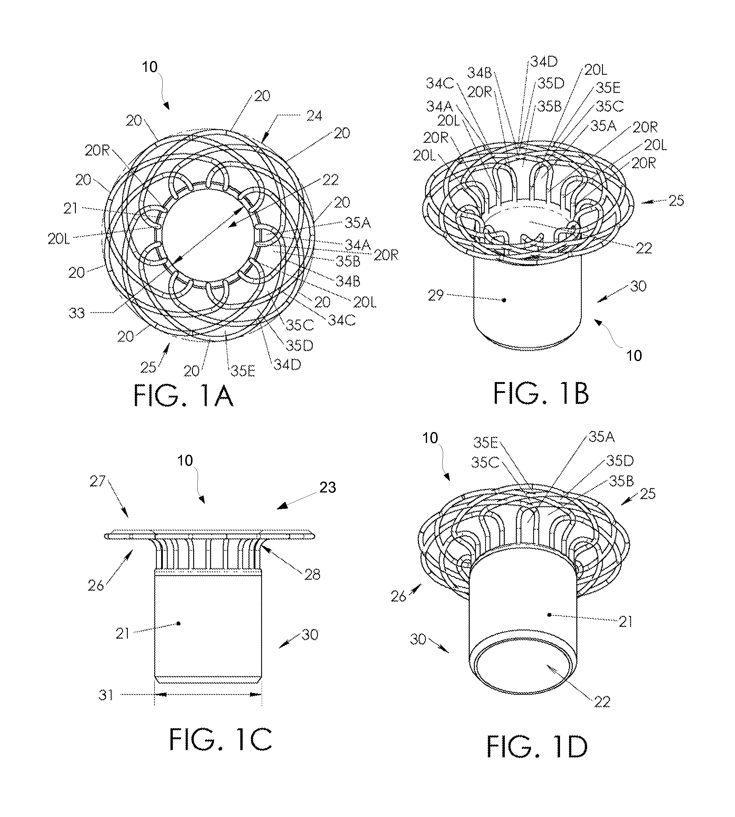
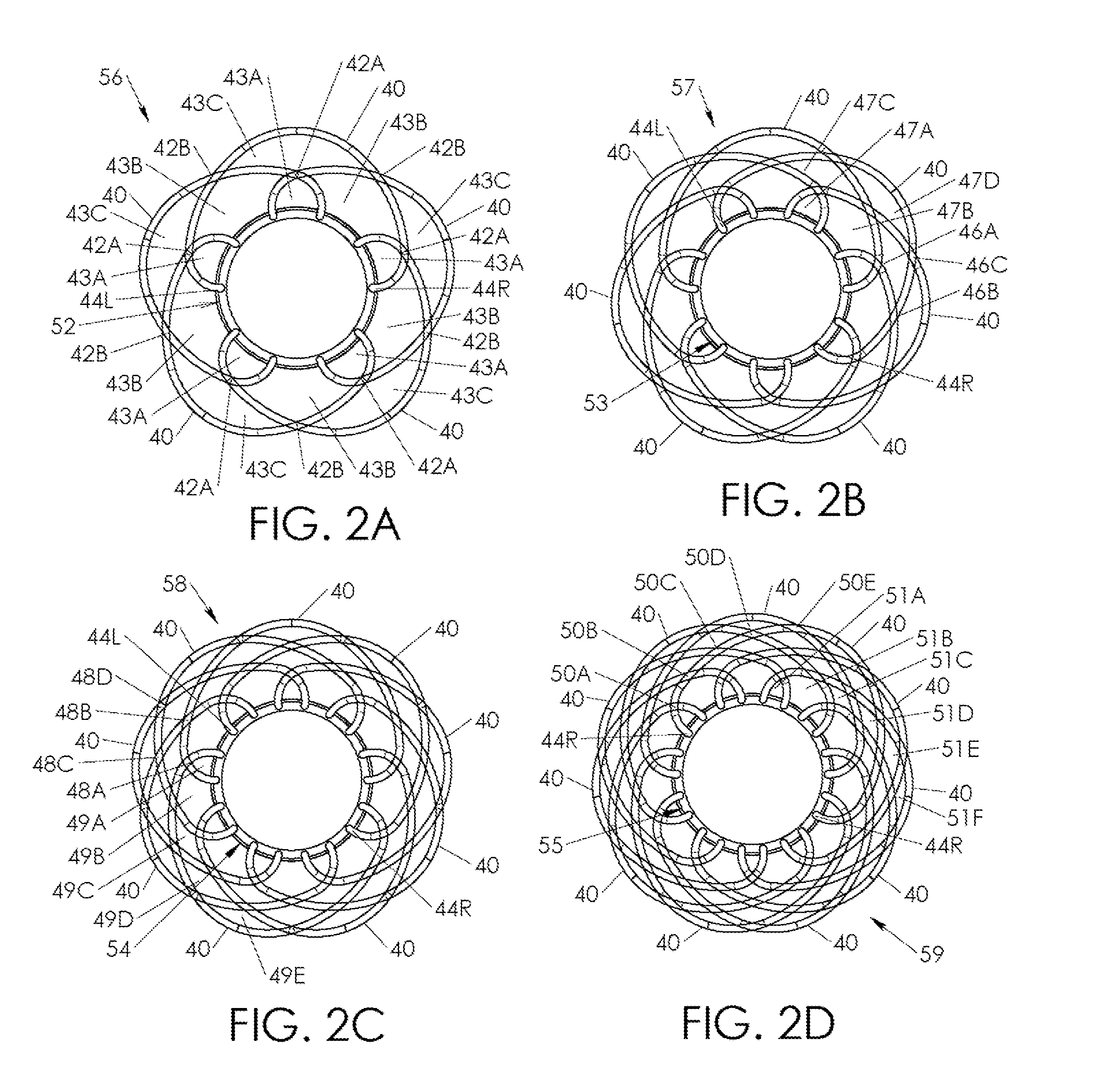
[0033]Referring to FIGS. 1A-1D a first embodiment of the cannula frame assembly 10 is shown. The cannula frame assembly 10 includes of an array of interwoven wires or wireforms 20 that are shaped and positioned relative to one another so as to form a flange assembly 25 at the distal end 23 of the assembly 10. The assembly 10 also includes and a tubular support b...


PUM


Abstract

Cannula assemblies and related methods are provided. In accordance with one embodiment, a cannula assembly includes a tubular structure coupled with a flange assembly. The flange assembly includes a plurality of wireform loops disposed in a circumferential, woven pattern about an end of the tubular structure. The flange assembly is configured to exhibit a first, collapsed state wherein the plurality of wireform loops extend substantially axially from the tubular structure, and a second, expanded state wherein the plurality of wireform loops extend in a direction having a substantial radial component relative to the tubular structure. In another embodiment, a cannula assembly includes a conformal flange coupled with a tubular structure, wherein the tubular structure extends both distally and proximally of the flange.

Description

CROSS-REFERENCE TO RELATED APPLICATIONS[0001]The present application claims priority to U.S. Provisional Application No. 61 / 370,360, filed on Aug. 3, 2010, entitled CONFORMAL CANNULA DEVICE, the disclosure of which is incorporated by reference herein in its entirety.TECHNICAL FIELD[0002]Exemplary embodiments relate to a connector for connection of a conduit to a vessel of the human body, and, more particularly to a cannula device adapted for attachment to a chamber of the heart and for blood passage therethrough, such as for transporting blood to a ventricular assist device (VAD).BACKGROUND[0003]Mechanical circulatory devices (MCDs) such as artificial hearts, ventricular assist devices (VADs) and other blood circulating systems and components have become increasingly recognized as life saving devices for patients whose heart is diseased or has been injured by trauma or heart attack or other causes. VADs in particular, are recognized as a major life saving modality for assisting pati...

Claims


Application Information

Patent Timeline
IPC IPC(8): A61M25/04
CPCA61F2/06A61M1/1008A61M1/10A61F2/064A61B2017/3425A61M60/863A61M60/178A61M60/859
Inventor VERKAIK, JOSIAH E.ANTAKI, JAMES F.MARTIN, JOHN ALEXANDER
Owner WORLD HEART
Learn More