
Method and apparatus for reducing block artifacts during image processing

Inactive Publication Date: 2012-06-07
SONY CORP
View PDF5 Cites 16 Cited by
  • Summary
  • Abstract
  • Description
  • Claims
  • Application Information

AI Technical Summary

Benefits of technology

[0008]Various embodiments of the present disclosure generally comprise a method and apparatus for reducing artifacts during image processing. In some embodiments, the method includes examining an input image comprising at least one source region, for each target region in an output

Problems solved by technology

The widespread usage of such image processing devices brings to light various defects.
These target regions can be unwanted or missing pixel regions for image processing.
The candidate patches are arbitrary because these devices cannot identify which source region pixels are needed to correctly inpaint the target region.
Since these devices employ a fixed or limited number of target regions, these devices are unable to define a flexible size and shape of the target region of each portion of an image to be inpainted.
Furthermore, processing and storing the images causes artifacts.
Artifacts, generally, include noticeable distortions of media (e.g., an image, audio and / or video) due to the application of an overly aggressive or inappropriate lossy data compression algorithm.
For example, certain block-based inpainting techniques cause these noticeable distortions.
The quantization of the individual image blocks is necessarily associated with a loss of information that can result in visible edges at the block boundaries during the reconstruction.

Method used


Image

  • Method and apparatus for reducing block artifacts during image processing
  • Method and apparatus for reducing block artifacts during image processing
  • Method and apparatus for reducing block artifacts during image processing

Examples


Embodiment Construction

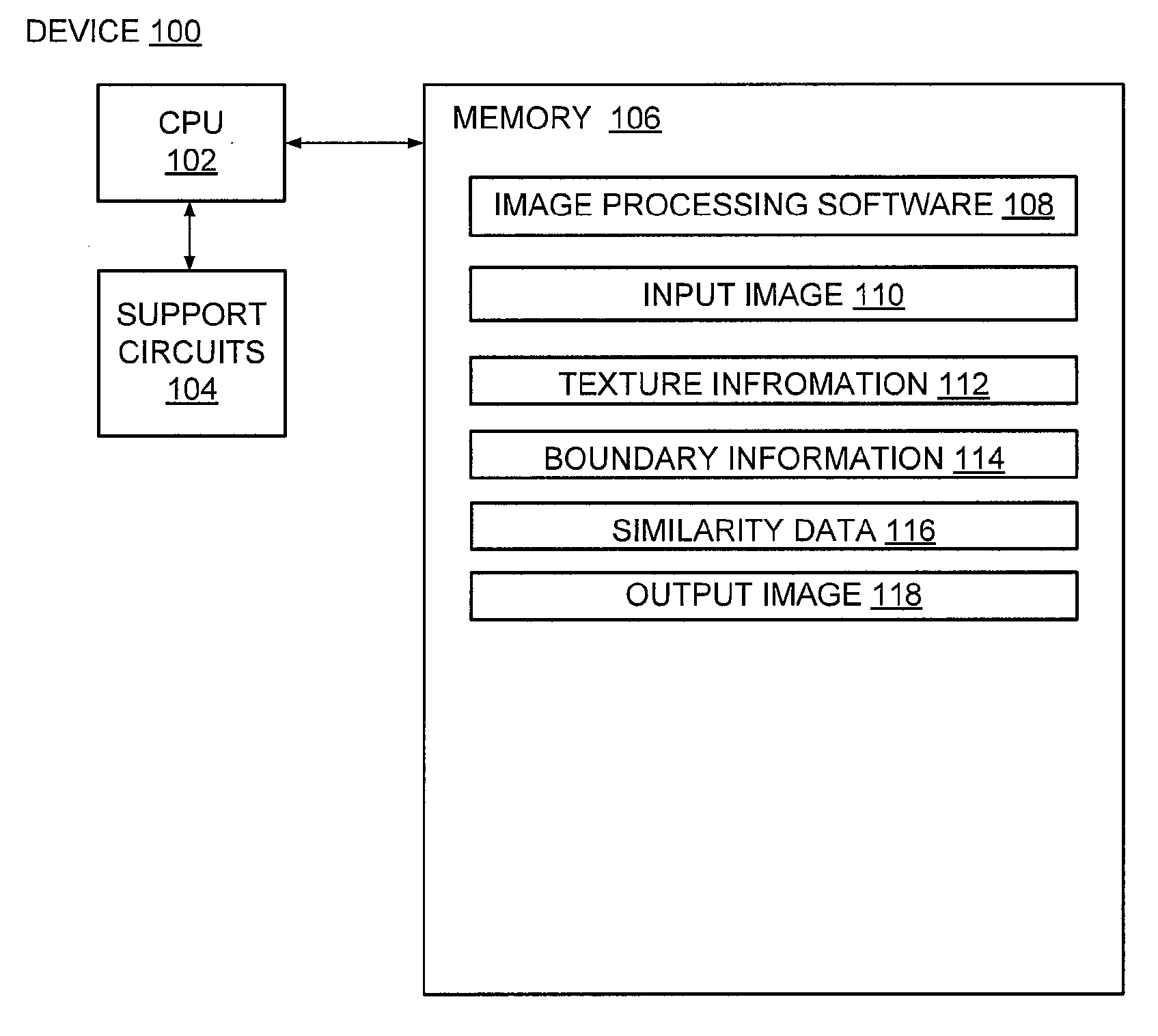
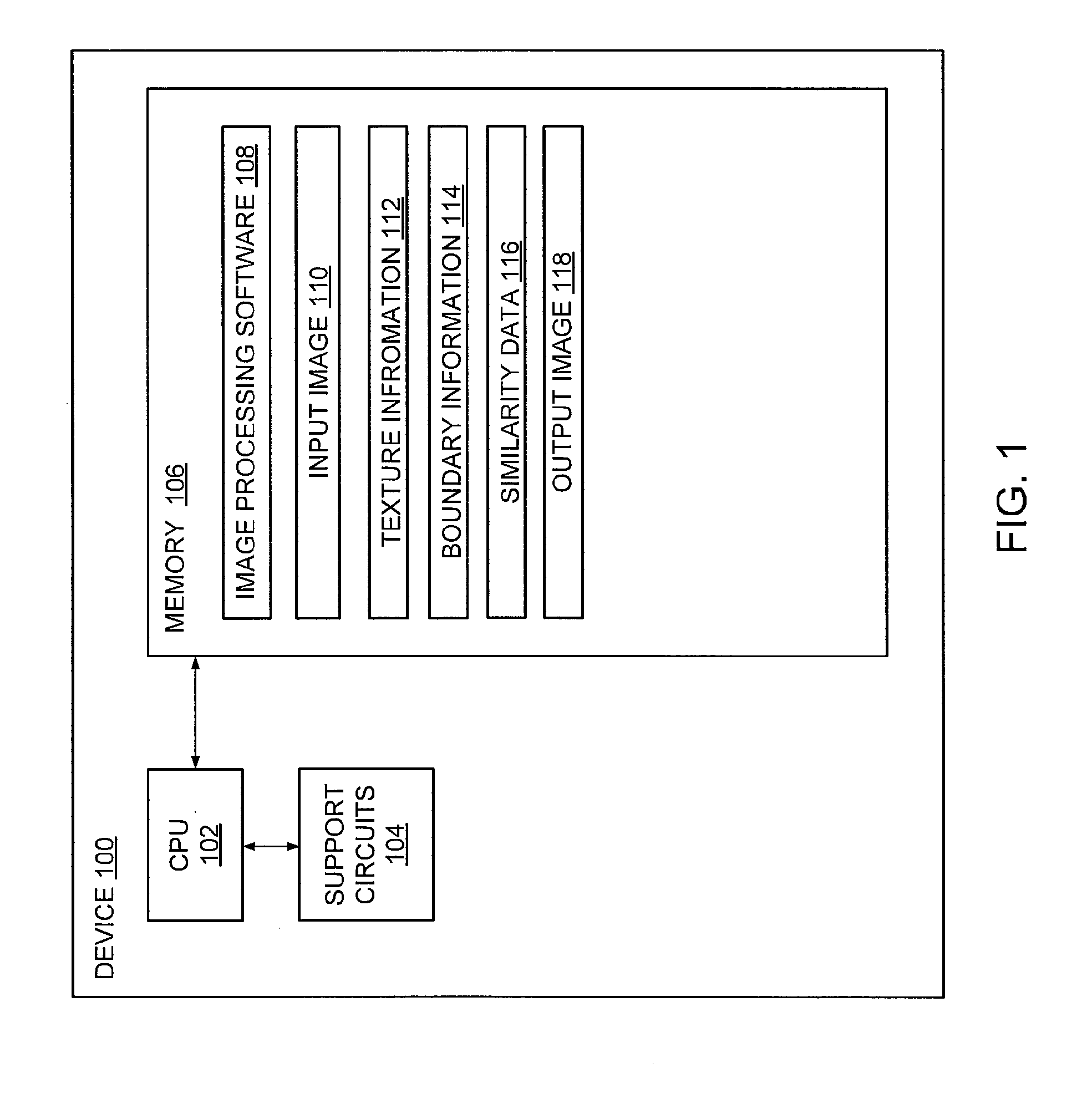
[0019]FIG. 1 illustrates a block diagram of a device 100 for reducing artifacts during image processing in accordance with at least one embodiment. Such a target region may be used for any image processing technique, such as 3-D scene generation 2D / 3D image magnification, image editing, compression, synthesis, object removal, 2D to 3D conversion and / or the like. The device 100 is a type of computing device (e.g., a laptop, a camera, a desktop, a server, a mobile device, a multimedia recording device and / or the like) that comprises a Central Processing Unit (CPU) 102, support circuits 104 and a memory 106. The CPU 102 comprises one or more commercially available microprocessors or microcontrollers that facilitate data processing and storage. The support circuits 104 facilitate operation of the CPU 102 and include clock circuits, buses, power supplies, input / output circuits and / or the like. The memory 106 includes a read only memory, random access memory, disk drive storage, optical s...


PUM


Abstract

A method and apparatus for reducing artifacts during image processing is described. In some embodiments, the method includes examining an input image comprising at least one source region, for each target region in an output image, identifying a portion of the at least one source region based on similarity data, defining an omnidirectional cut boundary and determining intensity values for the each target region and at least one pixel between the each target region and the omnidirectional cut boundary.

Description

BACKGROUND[0001]1. Technical Field[0002]Embodiments of the present disclosure generally relate to image processing systems and, more particularly, to a method and apparatus for reducing block artifacts during image processing.[0003]2. Description of the Related Art[0004]Image capturing and / or video recording devices constitute a significant portion of the current global consumer electronics market. The widespread usage of such image processing devices brings to light various defects. For example, these devices store images and / or video frames form target regions or unknown groups of pixels. These target regions can be unwanted or missing pixel regions for image processing. There may be a pet captured wandering in a background of a family portrait of which the user desires removal of that pet from any digital copies. As another example, several portions of an input image may be blended or combined into a graphical mesh in which instance the target regions include the resulting image....

Claims


Application Information

Patent Timeline
IPC IPC(8): G06K9/40
CPCG06T2207/20021G06T5/005G06T5/77
Inventor BAE, SOO HYUNXU, WENHUI
Owner SONY CORP
Learn More