
Structure of pneumatic impact wrench

Inactive Publication Date: 2012-06-07
STORM PNEUMATIC TOOL CO LTD
View PDF5 Cites 20 Cited by
  • Summary
  • Abstract
  • Description
  • Claims
  • Application Information

AI Technical Summary

Benefits of technology

[0011]Therefore, it is a primary objective of the present invention to overcome the aforementioned shortcomings of the prior art by providing an improved structure of a pneumatic impact wrench featuring a light weight and a sufficient structural strength, such that the pneumatic impact wrench can be manufactured with a lower cost and a better environmental protection without considering the precision of components, and the motor module can be installed precisely into the impact wrench.

Problems solved by technology

The main body 8 of the conventional impact wrench is generally made of aluminum, so that the structure of the conventional pneumatic impact wrench has the strength of a metal material and maintains a high precision of components, but aluminum is a lightweight metal with an appropriate strength and cannot be substituted by other metals easily when its cost is taken into consideration.
As a result, the total weight of the conventional impact wrench cannot be reduced easily, and a plastic main body is introduced to substitute the main body made of aluminum.
For example, a change of weather may cause a thermal expansion or contraction of the plastic material or an impact may cause a formation of the plastic material, so that a rotor 81′ installed in a containing space 80′ may not be operated smoothly, and the performance of the impact wrench is affected adversely.
However, the related surface treatment generally causes a severe pollution to the environment. in addition to its drawback of high manufacturing cost.

Method used


Image

  • Structure of pneumatic impact wrench
  • Structure of pneumatic impact wrench
  • Structure of pneumatic impact wrench

Examples


Embodiment Construction

[0021]The foregoing and other objectives, characteristics and advantages of the present invention will become apparent by the detailed description of a preferred embodiment as follows. It is noteworthy to point out that each preferred embodiment is provided for the purpose of illustrating the present invention only. but not intended for limiting the scope of the patent claims.

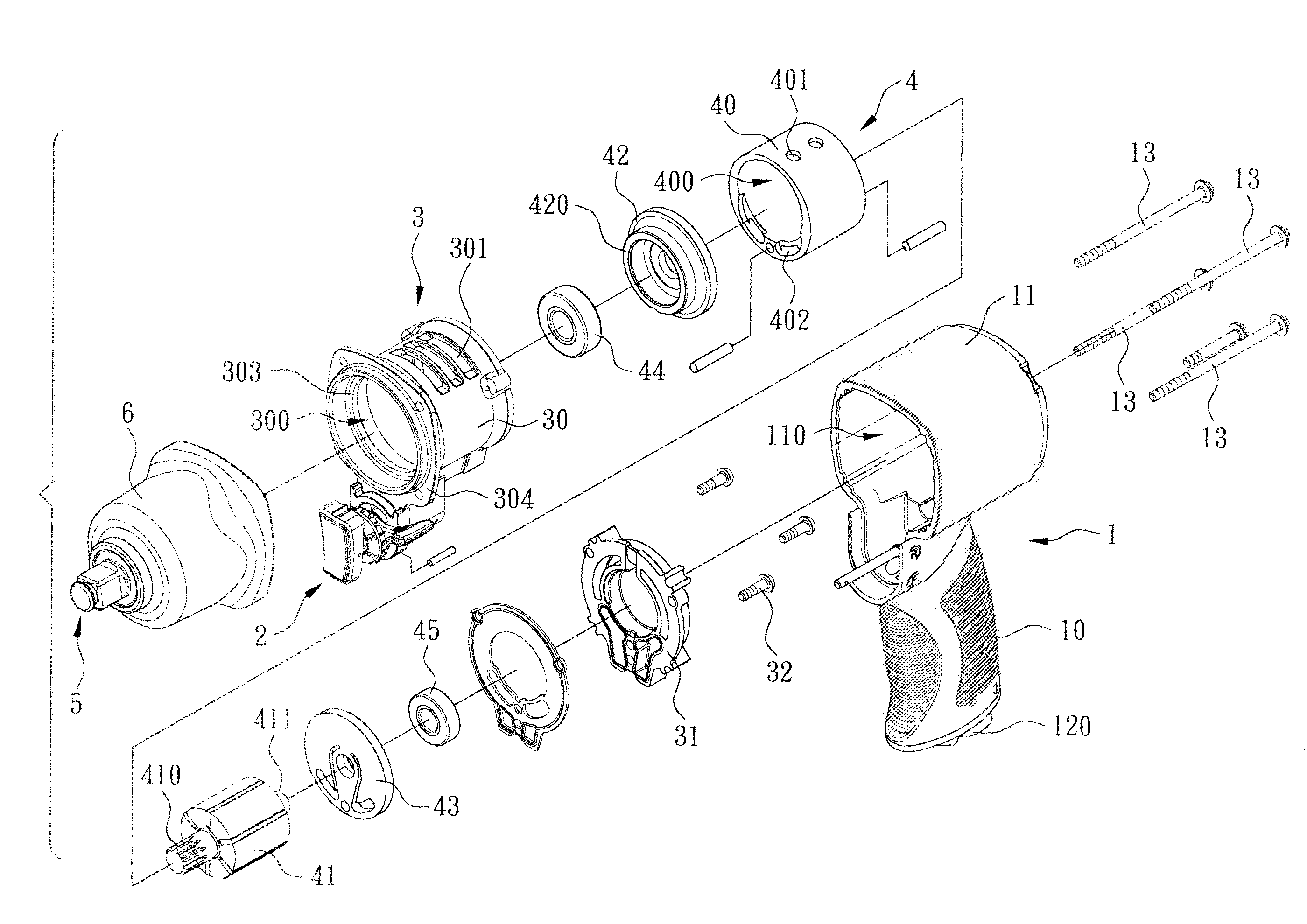
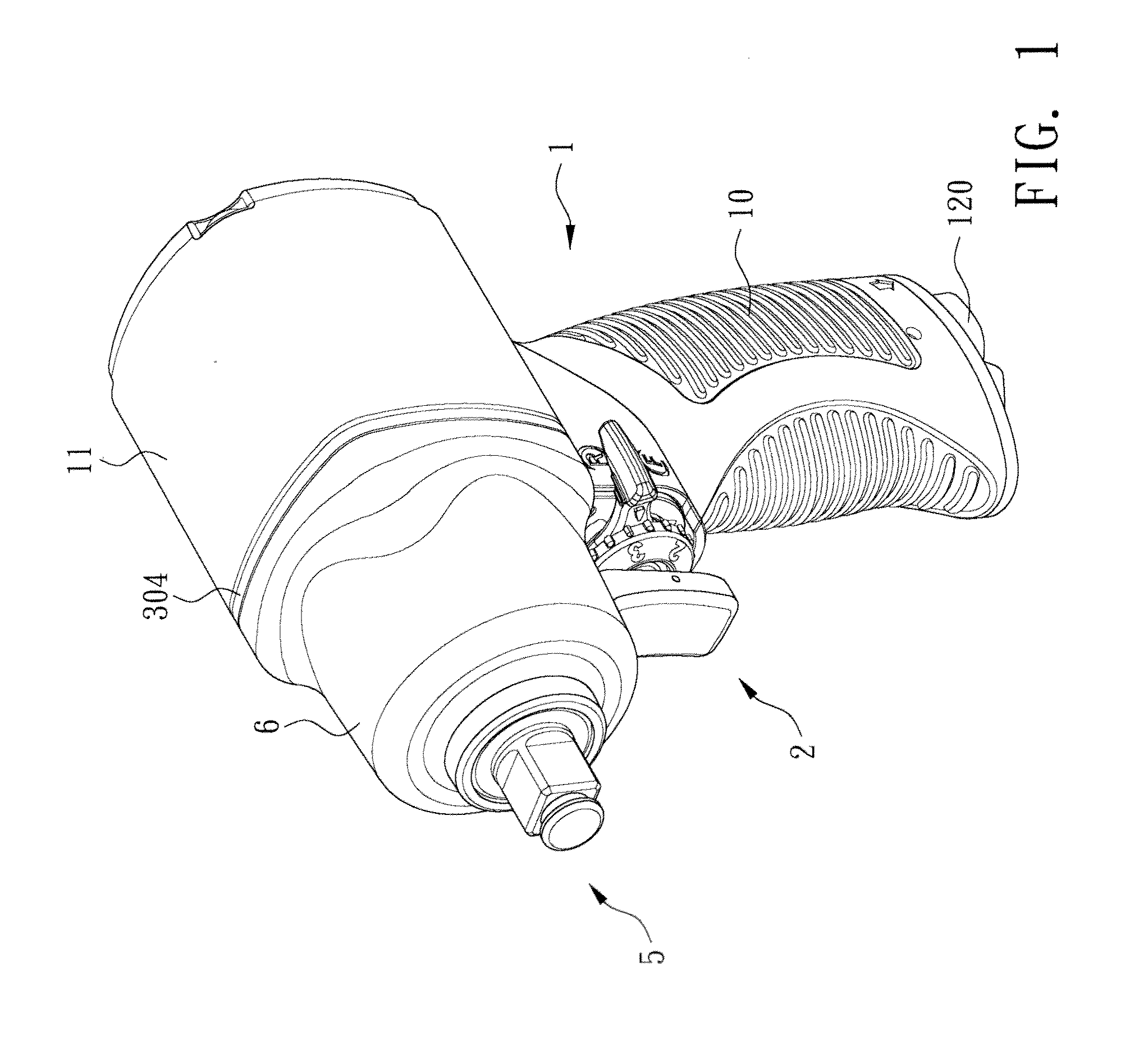
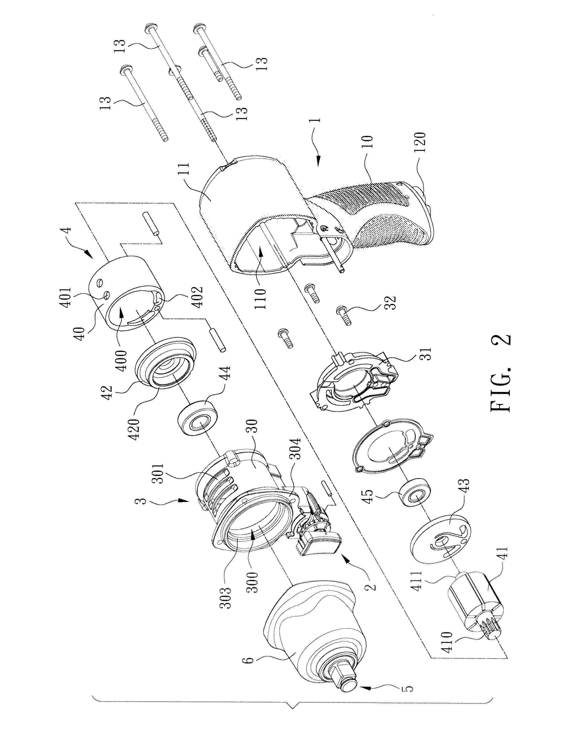
[0022]With reference to FIGS. 1 and 2 for an improved structure of a pneumatic impact wrench in accordance with a preferred embodiment of the present invention, the pneumatic impact wrench comprises a main body 1, a switch module 2, a motor casing 3, a motor module 4, and an impact module 5.

[0023]In FIGS. 2 and 3. the main body 1 includes a handle 10, and a plastic casing 11 coupled to a top end of the handle 10, and the handle 10 and the plastic casing 11 are integrally formed as a whole, and the handle 10 includes an air intake passage 12 formed therein and extended from the interior of the handle to the inte...


PUM

PropertyMeasurementUnit
Structureaaaaaaaaaa
Hardnessaaaaaaaaaa

Abstract

An improved structure of a pneumatic impact wrench includes a main body, a plastic casing provided for fixing a motor casing and a motor module, the motor module having a cylinder for installing a rotor, the rotor being extended from an axle and supported by a bearing, the motor casing having an external case with a hardness greater than that of the plastic casing, and the external case being hollow and penetrating both ends to form a chamber for accommodating and installing a cylinder, and the external case having a stop ring protruded from an internal wall of the chamber and provided for blocking the cylinder, and an external case cover installed at a rear end of the external case for coupling and covering the external case cover.

Description

BACKGROUND OF THE INVENTION[0001]1. Field of the Invention[0002]The present invention relates to a pneumatic tool, and more particularly to an improved structure of a pneumatic impact wrench.[0003]2. Description of the Related Art[0004]With reference to FIG. 5 for a perspective view of a main body of a conventional pneumatic impact wrench, the conventional pneumatic impact wrench comprises a main body 8, a containing space 80 formed in the main body 8 for installing and accommodating a rotor 81, and other components such as a driving module (not shown in the figure). The main body 8 of the conventional impact wrench is generally made of aluminum, so that the structure of the conventional pneumatic impact wrench has the strength of a metal material and maintains a high precision of components, but aluminum is a lightweight metal with an appropriate strength and cannot be substituted by other metals easily when its cost is taken into consideration. As a result, the total weight of the...

Claims


Application Information

Patent Timeline
IPC IPC(8): B25B21/02B25F5/02
CPCB25F5/02B25B21/02
Inventor SUN, YUNG-YUNGCHENG, CHUAN-CHING
Owner STORM PNEUMATIC TOOL CO LTD
Learn More