
Devices and Methods for Treating Bone

a bone and bone technology, applied in the field of bone devices and methods, can solve the problems of reducing bone density, affecting bone health, and affecting bone health, and preventing bone fractures

Active Publication Date: 2012-05-31
GLOBUS MEDICAL INC
View PDF6 Cites 55 Cited by
  • Summary
  • Abstract
  • Description
  • Claims
  • Application Information

AI Technical Summary

Problems solved by technology

Osteoporosis reduces bone density, thereby weakening bones and predisposing them to fracture.
While the fractures may heal without intervention, the crushed bone may fail to heal adequately.
Spinal deformity may lead to breathing and gastrointestinal complications, and adverse loading of adjacent vertebrae.
Commonly, they cause loss of height and a humped back.
In severe cases, the body's center of mass is moved further away from the spine resulting in increased bending moment on the spine and increased loading of individual vertebrae.
When cancer cells spread to the spine, the cancer may cause destruction of part of the vertebra, weakening and predisposing the bone to fracture.
Osteoporosis and metastatic disease are common root causes leading to vertebral fractures, but trauma to healthy vertebrae also causes minor to severe fractures.
Such trauma may result from a fall, a forceful jump, a car accident, or any event that stresses the spine past its breaking point.
However, they often cause a severe “band-like” pain that radiates from the spine around both sides of the body.
It is commonly believed that the source of acute pain in compression fractures is the result of instability at the fracture site, allowing motion that irritates nerves in and around the vertebrae.
However, it is difficult to consistently attain meaningful height restoration.
It appears the inconsistent results are due, in part, to the manner in which the balloon expands in a compressible media and the structural orientation of the trabecular bone within the vertebra.
For example, it has been found that expansion of the balloon-like device can be difficult to control.
As a result, the direction of compaction of the cancellous bone and / or reduction of the compression fracture is not controllable, and expansion occurs in multiple directions and along multiple axes.

Method used


Image

  • Devices and Methods for Treating Bone
  • Devices and Methods for Treating Bone
  • Devices and Methods for Treating Bone

Examples


Embodiment Construction

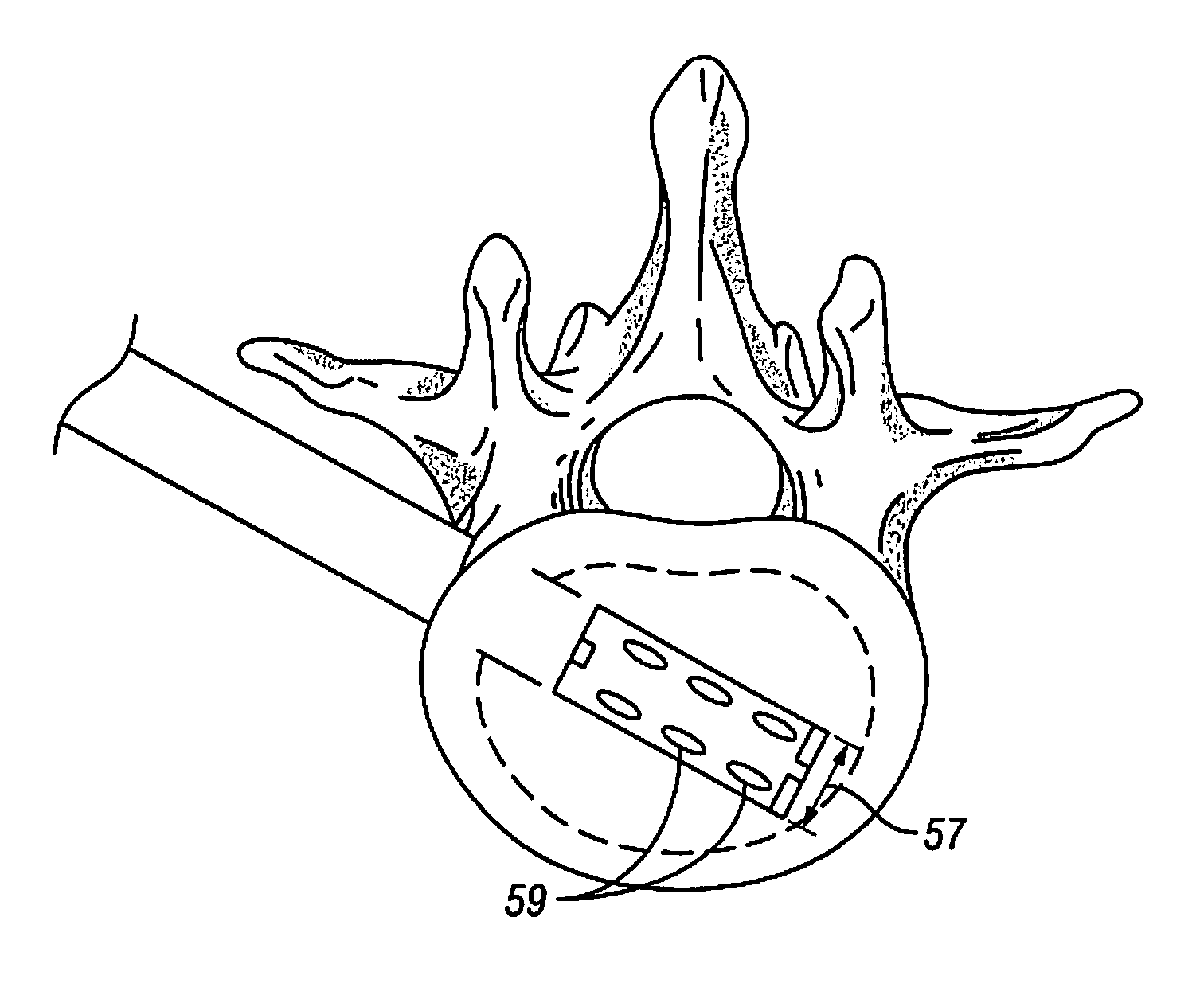
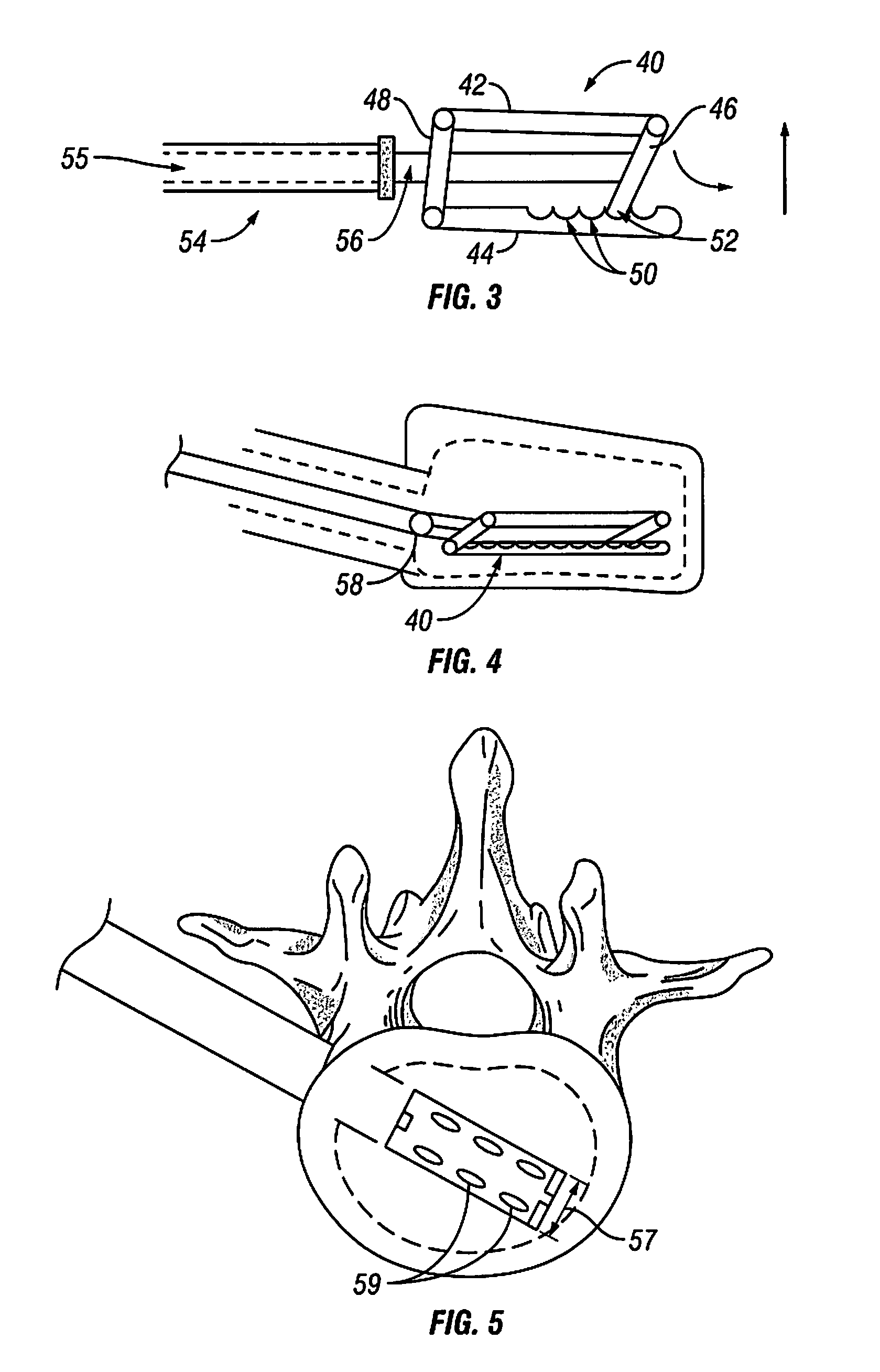
[0036]Embodiments of the present invention are generally directed to devices and methods for creating a cavity in bone. In particular, certain embodiments are directed to minimally invasive distraction and support devices and methods to treat bone fractures.

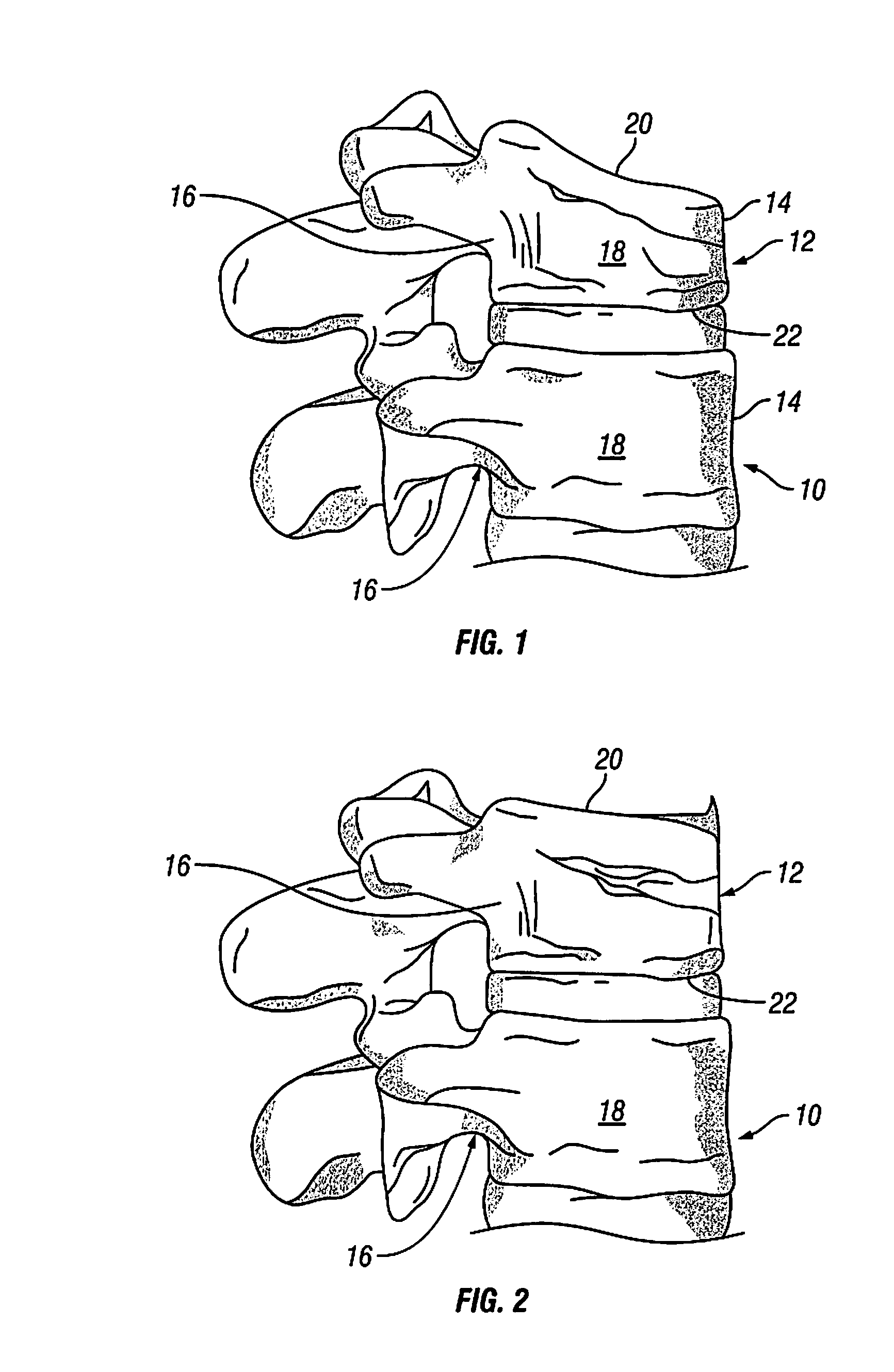
[0037]The devices and methods are generally described by its application to the vertebral compression fracture. FIG. 1 illustrates two vertebrae 10, 12, each with an anterior side 14, a posterior side 16, and lateral sides 18 (only one shown). Vertebra 10 is fully intact, while vertebra 12 has a vertebral compression fracture (i.e., the top 20 and bottom 22 of the vertebra have been displaced towards each other). Referring to FIG. 2) the vertebral compression fracture of vertebra 12 is shown in a reduced or height restored state (i.e.) the top 20 and bottom 22 of the vertebra 12 are distracted or displaced back to or near their original intact positions). It is known that the force required to reduce the vertebral compression fra...


PUM

PropertyMeasurementUnit
Flow rateaaaaaaaaaa

Abstract

A device is disclosed for reducing a vertebral compression fracture, comprising a superior end plate and an inferior end plate disposed along a vertical axis. The superior end plate and the inferior end plate are slidably separable in a vertical direction along the vertical axis. An interior chamber is provided in fluid communication with a port extending from an exterior to the interior chamber. The device is deployable within a vertebral body and expandable within the vertebral body by injecting a flowable material into the interior chamber thereby displacing the superior and inferior end plates along the vertical axis.

Description

CROSS REFERENCE TO RELATED APPLICATIONS[0001]This patent application is a continuation application claiming priority to U.S. patent application Ser. No. 12 / 201,112, filed on Aug. 29, 2008, the entire contents of which are incorporated by reference.FIELD OF THE INVENTION[0002]The present invention generally relates to devices and methods for treating bone. In particular, certain embodiments are directed to minimally invasive distraction and support devices and devices and methods to treat bone fractures.BACKGROUND OF THE INVENTION[0003]A minimally invasive distraction and support device and method would have significant application in orthopaedic surgical procedures, including acute and elective procedures to treat bone fractures and degenerative changes of the skeletal system and including vertebral compression fractures, interbody fusion, vertebral disc augmentation or replacement, and other compression fractures and / or non-orthopaedic surgical procedures.[0004]A vertebral compress...

Claims


Application Information

Patent Timeline
IPC IPC(8): A61F2/44
CPCA61B17/1617A61B17/7095A61B17/8852A61F2002/2835A61B17/8858A61F2/44A61B17/8855A61B17/025A61B17/1671A61B2017/0256A61F2/441A61F2/442A61F2/4455A61F2002/30471A61F2002/3052A61F2002/30556A61F2002/30583A61F2002/30593A61F2002/30601A61F2002/4415A61B17/66A61B17/8805
Inventor SEIFERT, JODY LMILLHOUSE, PAUL W.CALVERLEY, JAMIEBOYER, II, MICHAEL LEEPATEL, NIRALIANKNEY, DAVID W.ADAMS, MARK
Owner GLOBUS MEDICAL INC
Learn More