
Connection structure between thin wall stainless steel pipe and joint

a technology of stainless steel pipe and connection structure, which is applied in the direction of flanged joints, fluid pressure sealed joints, sleeve/socket joints, etc., can solve the problems of a large burden on the material supply of both the manufacturer and the joint, and achieve the effect of small storage space, small size, and cheap manufacturing

Active Publication Date: 2012-05-31
ON IND
View PDF7 Cites 0 Cited by
  • Summary
  • Abstract
  • Description
  • Claims
  • Application Information

AI Technical Summary

Benefits of technology

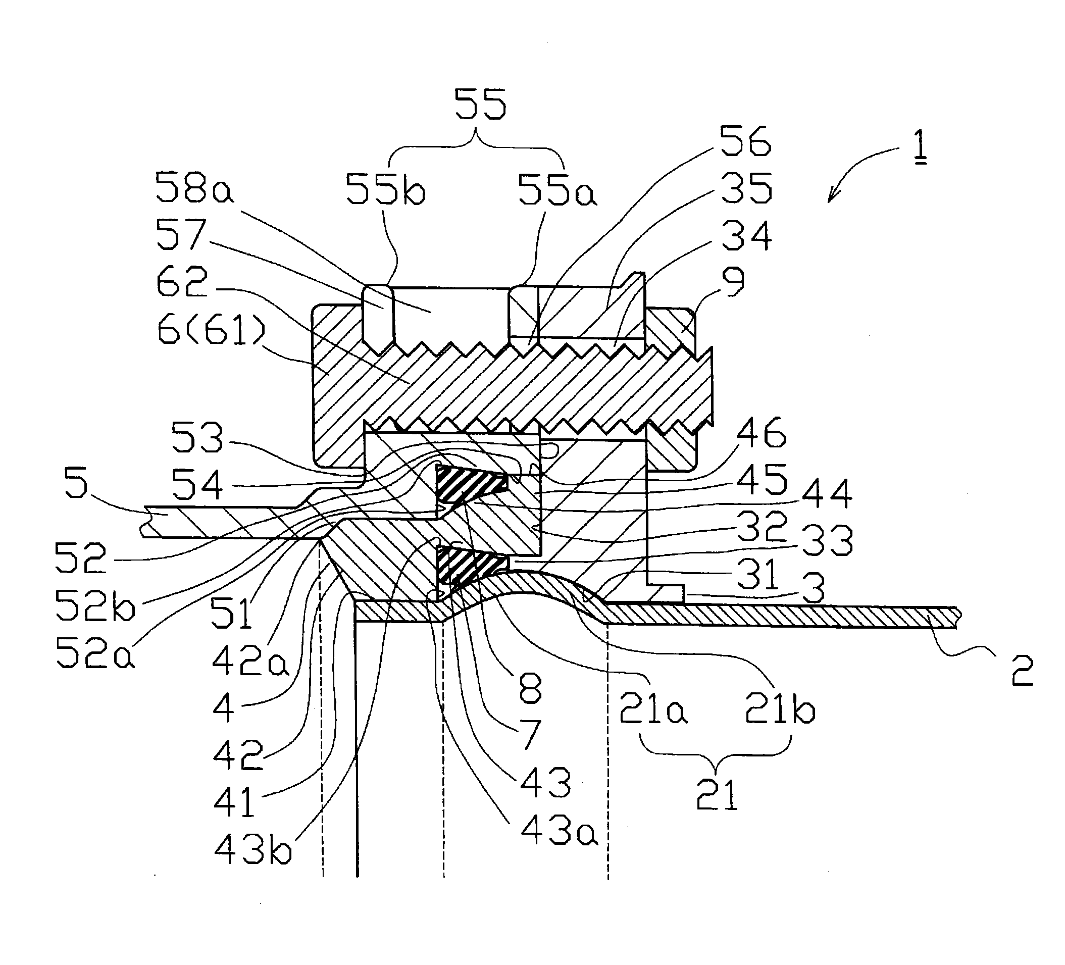
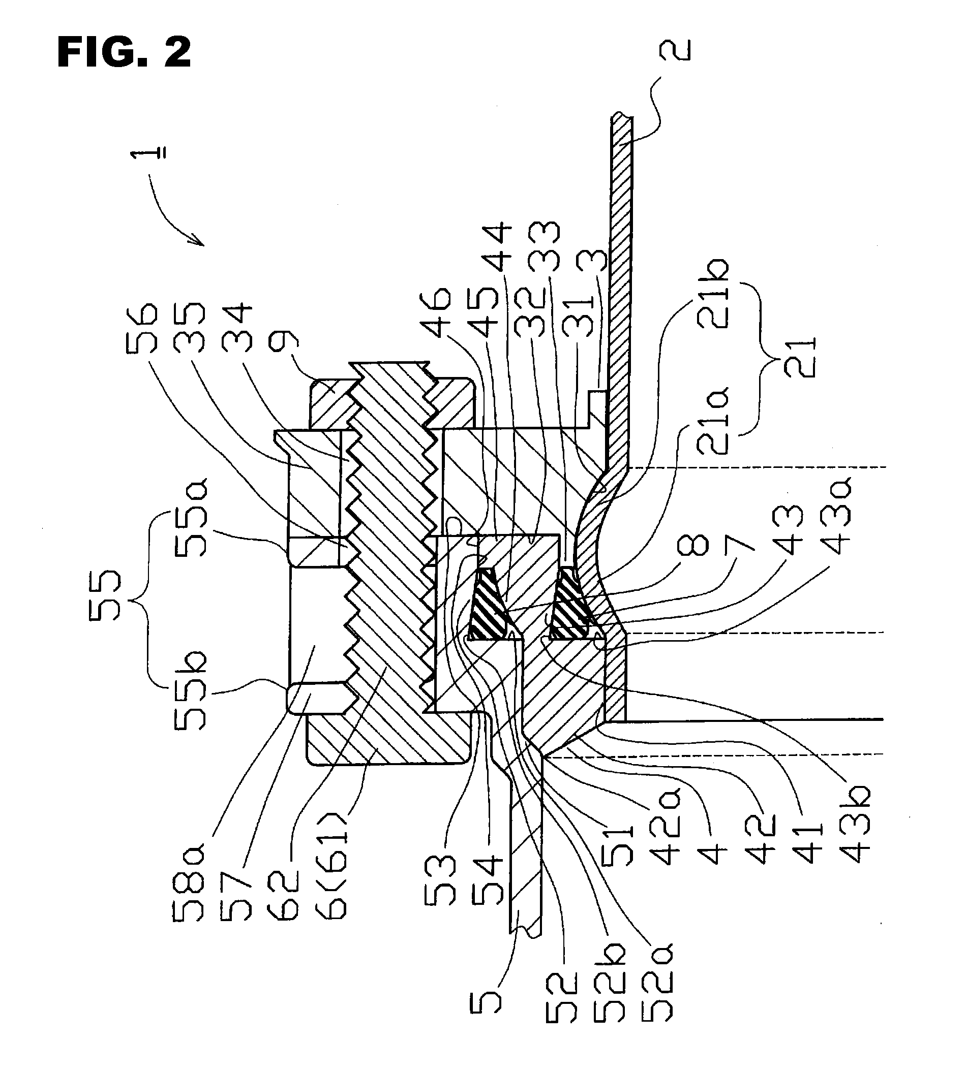
[0013]The connection structure between the thin wall stainless steel pipe and the joint according to the first aspect can connect the joint, and the thin wall stainless steel pipe having the pipe diameter which is different from the pipe diameter of the joint, while having airtightness. Accordingly, the present connection structure can connect the thin wall stainless steel pipes in which the pipe diameters are different from each other, by using the general purpose joint. In the present connection structure, the joint spacer is used, and it is necessary to prepare many kinds of joint spacers depending on the pipe diameters of the thin wall stainless steel pipes. However, since the joint spacer can be manufactured inexpensively as compared with the joint, and is small in size, there is such a feature that the storage place can be made small, and the joint spacer is convenient for transporting. Accordingly, the burden of the manufacturer and the consumer can be reduced as compared with the case where many kinds of joints are prepared. Further, in the present connection structure, since the protruding portion formed in the inner peripheral side of the inner end surface of the sandwiching portion is pinched by the first retention portion formed in the joint spacer fitted to the joint, it is easy to position the sandwiching portion and the joint. This has such an effect of improving a working property at the time of connecting the thin wall stainless steel pipe and the joint. Further, since the inner end surface of the sandwiching portion comes into contact with the joint spacer and the contact surface of the joint, it is possible to prevent the first gasket and the second gasket from being broken by fastening the bolt too much.
[0015]In the connection structure between the thin wall stainless steel pipe and the joint according to the third aspect, the rotation preventing device of the bolt head is provided in the end surface in the side opposite to the sandwiching portion of the rear flange. Since the bolt is inhibited by the rotation preventing device from rotating at the time of fastening and coupling the flange portion of the joint and the flange portion of the sandwiching portion by the nut, a working property of the work with respect to the fastening and coupling is improved.
[0016]In the connection structure between the thin wall stainless steel pipe and the joint according to the fourth aspect, one or more projections or depressions are formed in a side opposed to the sandwiching portion, in the first gasket. Since the projection or the depression becomes a marker for checking the front and back of the first gasket by a visual sense or a tactile sense at the time of arranging the first gasket in the first retention portion, it is possible to prevent the front and back of the first gasket from being arranged erroneously in the first retention portion.
[0017]In the connection structure between the thin wall stainless steel pipe and the joint according to the fifth aspect, one or more projections or depressions are formed in a side opposed to the sandwiching portion, in the second gasket. Since the projection or the depression becomes a marker for checking the front and back of the second gasket by a visual sense or a tactile sense at the time of arranging the second gasket in the second retention portion, it is possible to prevent the front and back of the second gasket from being arranged erroneously in the second retention portion.

Problems solved by technology

However, there is a case where it is necessary to connect the thin wall stainless steel pipes having the different pipe diameters by using the joint.
This matter is a great burden to both a manufacturer supplying the joint, and a consumer using the joint, in view of a manufacturing cost, a storage space or the like.

Method used


Image

  • Connection structure between thin wall stainless steel pipe and joint
  • Connection structure between thin wall stainless steel pipe and joint
  • Connection structure between thin wall stainless steel pipe and joint

Examples


Embodiment Construction

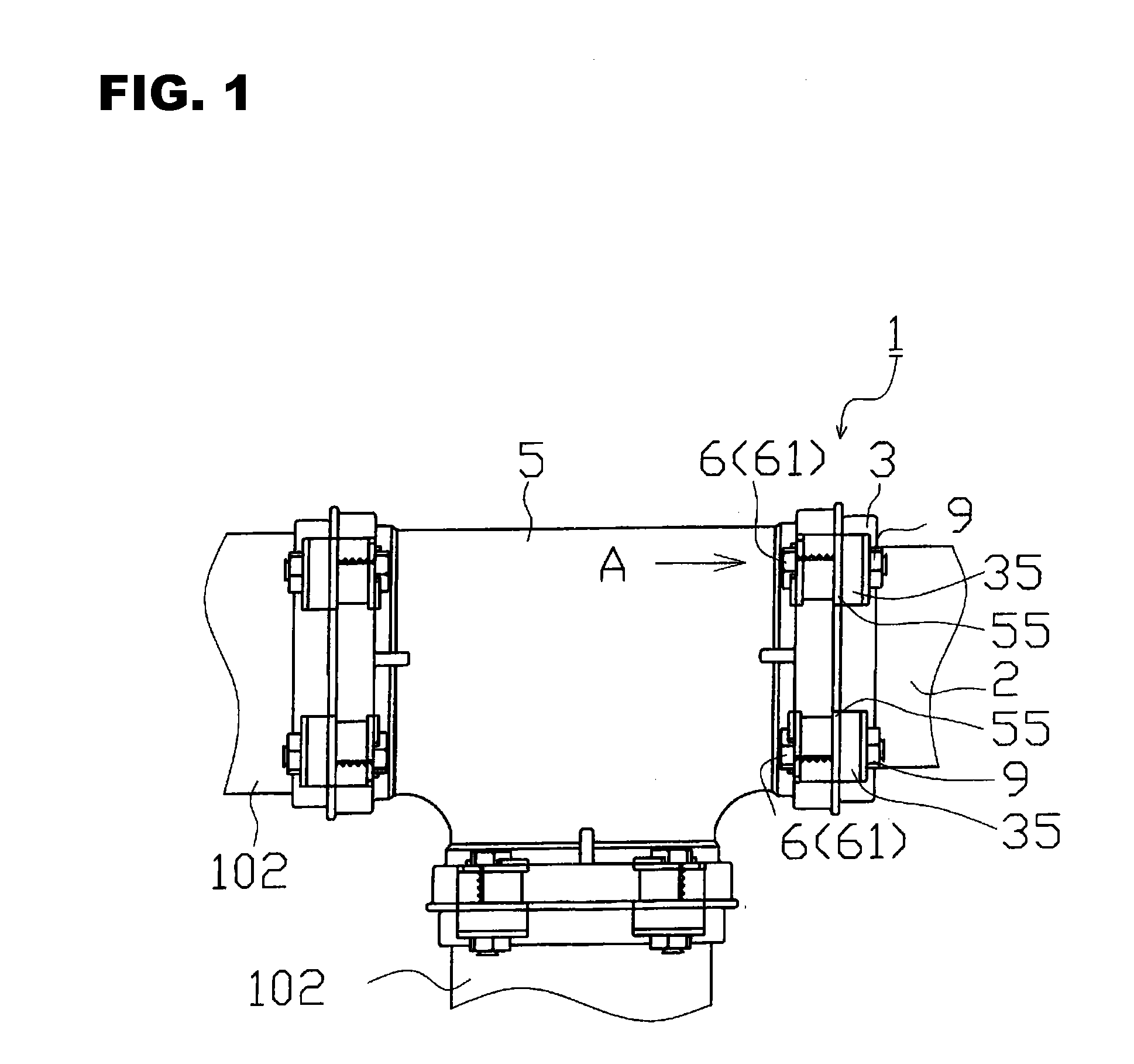
[0025]Hereinafter, an embodiment of the present invention will be described with reference to the accompanying drawings. A connection structure between a thin wall stainless steel pipe and a joint (hereinafter, simply referred to as “connection structure”) 1 is mainly constructed by a thin wall stainless steel pipe 2, a sandwiching portion 3, a joint spacer 4, a joint 5 and a bolt 6. The connection structure 1 can connect the joint 5, and the thin wall stainless steel pipe 2 having a pipe diameter which does not comply with the joint 5 while holding airtightness.

[0026]As shown in FIG. 2, the thin wall stainless steel pipe 2 is a steel pipe which is made of a stainless steel and has a pipe thickness between 0.7 mm and 3 mm, and a swelling portion 21 which is constructed by two inclined surfaces 21a and 21b and swells annularly in an outside direction is formed in an outer periphery of an end portion of the steel pipe.

[0027]The sandwiching portion 3 is externally fitted to an end port...


PUM


Abstract

A connection structure includes a thin wall stainless steel pipe in which a swelling portion, a sandwiching portion forming an inclined pressing surface capable of pressing one inclined surface of the swelling portion, a joint spacer forming a first retention portion pinching a first gasket with respect to the swelling portion as well as having a fitting portion fitted to an outer periphery of the end portion of the thin wall stainless steel pipe, and forming a gasket receiving portion in an outer peripheral side thereof, a joint having a second retention portion sandwiching and pressing a second gasket to an inner peripheral side facing the gasket receiving portion.

Description

BACKGROUND OF THE INVENTION[0001](1) Field of the Invention[0002]The present invention relates to a connection structure between a thin wall stainless steel pipe and a joint, and more particularly to a connection structure between a thin wall stainless steel pipe and a joint which can connect a joint, and a thin wall stainless steel pipe having a pipe diameter which is different from and does not comply with a pipe diameter of the joint while holding airtightness.[0003](2) Description of Related Art[0004]Since the thin wall stainless steel pipe is excellent in durability or the like, it is used for various intended uses including purposes for supplying water, supplying hot water and supplying cold and hot water. This thin wall stainless steel pipes having the various pipe diameters are prepared so as to be selectable depending on the intendeduse or the like. However, there is a case where it is necessary to connect the thin wall stainless steel pipes having the different pipe diamet...

Claims


Application Information

Patent Timeline
IPC IPC(8): F16L23/00
CPCF16L23/22F16L23/0283
Inventor OHARA, KOJIASHIDA, HIROSHI
Owner ON IND
Learn More