Cutting machine with a liquid lubrication delivery system having a controlled liquid level

a technology of liquid lubrication and cutting machine, which is applied in the direction of metal sawing accessories, working accessories, manufacturing tools, etc., can solve the problems of overspray, affecting the cutting process, so as to promote liquid flow, minimize overspray, and maintain constant level and velocity

Active Publication Date: 2012-05-17
HUSQVARNA AB
View PDF23 Cites 29 Cited by
  • Summary
  • Abstract
  • Description
  • Claims
  • Application Information

AI Technical Summary

Benefits of technology

The present disclosure is about a cutting machine with a liquid lubrication delivery system. The machine has a work-piece platform with a main channel that has a liquid delivery portion at the beginning and a liquid leveler portion at the end. The main channel has at least one liquid lubrication inlet that discharges lubricant into the channel. The machine also has at least one nozzle that supplies lubricant to the blade. The nozzle can be located below the blade or on a cross-member portion of the machine. The main channel has a perimeter that receives the blade during cutting operations. The liquid lubrication delivery system helps to cool and lubricate the cutting blade, remove debris from the main channel, and provide an adequate sweeping flow. The invention provides a cutting machine with improved lubrication capabilities for efficient cutting operations.

Problems solved by technology

Such heat can be damaging to the blade.
Although heat damage is reduced by the cooling, part of the blade is always submerged in the water, which can be damaging.
Although these systems eliminate submersion of the blade in a water basin, a new problem of overspray arises.
As the nozzles spray water against the rotating blade, water is splashed off the blade creating a mess in the work area and wetting the operator.
Furthermore, this system wastes water because much of the water is splashed off of the blade before it can properly cool the blade.
These solutions, however, still use more water than necessary to cool the blade and leave the top of the work-piece soaked.
Additionally, debris and dust from cutting the work-piece can build up on the work table and on the cutting blade.

Method used


Image

  • Cutting machine with a liquid lubrication delivery system having a controlled liquid level
  • Cutting machine with a liquid lubrication delivery system having a controlled liquid level
  • Cutting machine with a liquid lubrication delivery system having a controlled liquid level

Examples


Embodiment Construction

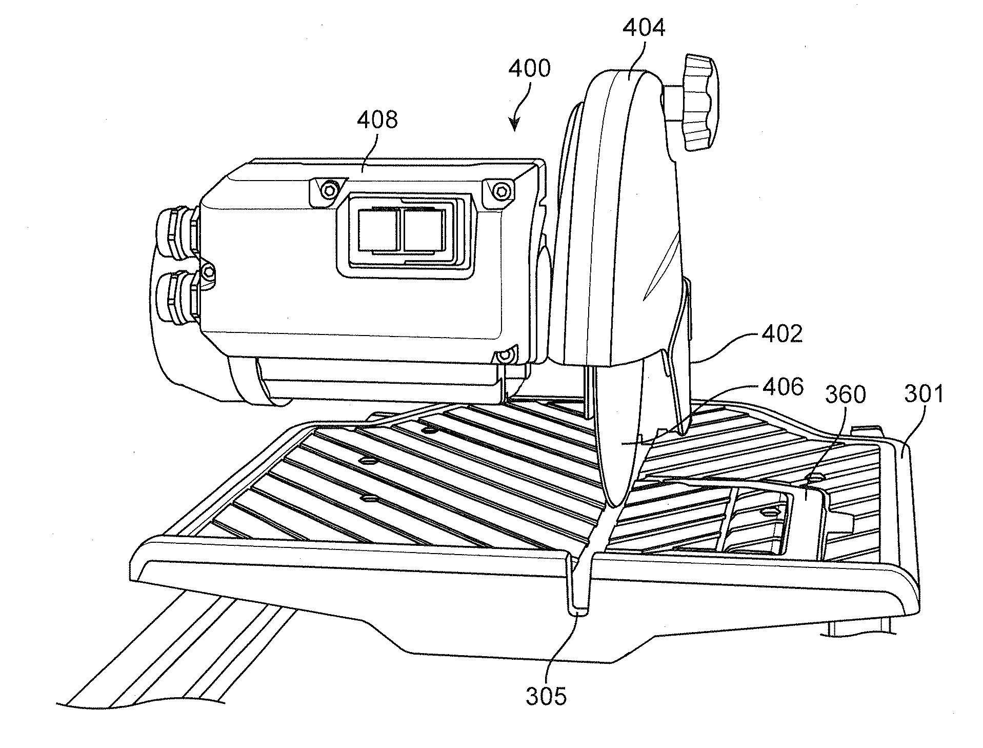
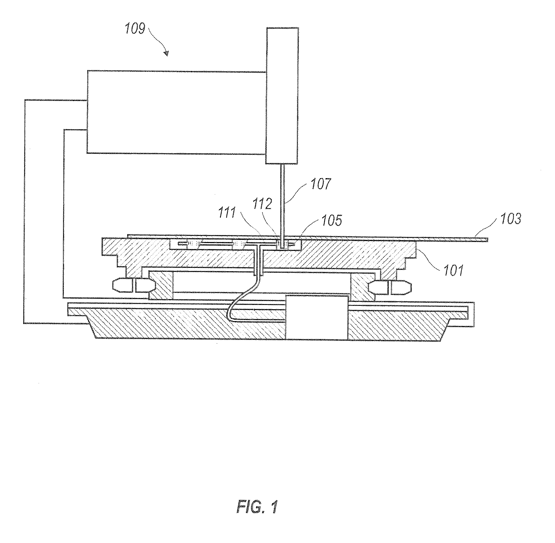
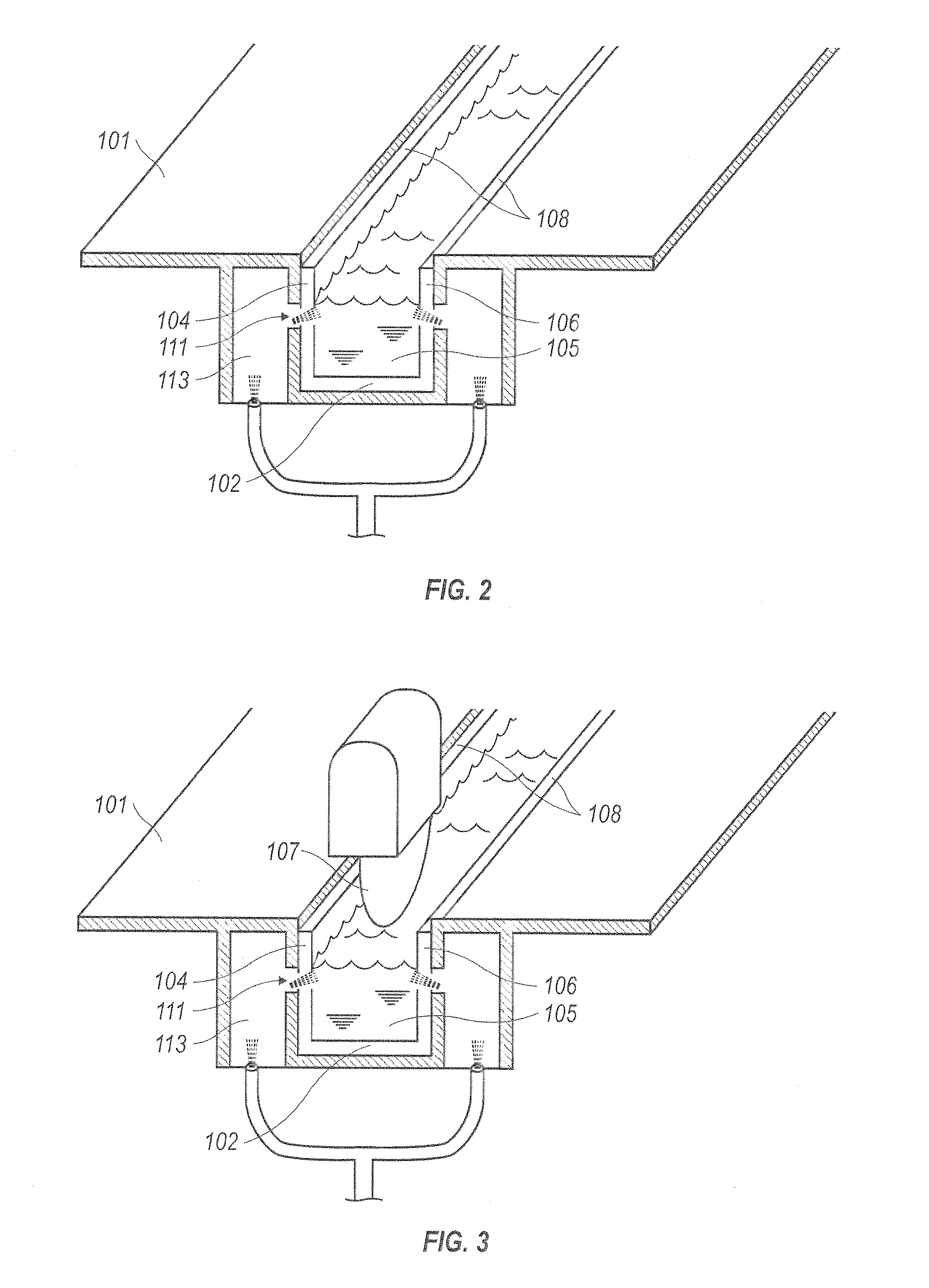
[0046]A cutting machine having a liquid lubrication delivery system configured according to the present teachings will hereinafter be described more fully with reference to the accompanying drawings in which preferred embodiments of the system are illustrated. Additionally, as described herein, the present disclosure presents a work-piece platform. The work-piece platform can include an upper surface for supporting a work-piece. The work-piece platform can further include a main channel defining a recess in the upper surface. At least one liquid lubrication inlet for discharging liquid into the main channel can also be present on the work-piece platform. Additional features of the work-piece platform and cutting machine are This system can, however, be embodied in many different forms and should not be construed as limited to the embodiments set forth herein. Rather, these embodiments are provided so that this disclosure will be thorough and complete, and will fully convey the scope...


PUM

PropertyMeasurementUnit
angleaaaaaaaaaa
sizeaaaaaaaaaa
anglesaaaaaaaaaa

Abstract

A cutting machine having a liquid lubrication delivery system. The machine includes a work-piece platform having an upper surface for supporting a work-piece thereupon. The work-piece platform can further include a main channel defining a recess in the upper surface. At least one liquid lubrication inlet for discharging liquid into the main channel can also be present on the work-piece platform. The at least one liquid lubrication inlet can be a plurality of liquid lubrication inlets.

Description

CROSS-REFERENCE TO RELATED APPLICATIONS[0001]The present application is a continuation-in-part application of PCT / US2010 / 027691 filed Mar. 17, 2010, which claims priority to International Application No. PCT / US2009 / 037352, filed 17 Mar. 2009, said applications are hereby incorporated by reference in their entirety.FIELD[0002]The invention relates to the field of cutting machines, and more particularly, to cutting machines including a liquid lubrication delivery system.BACKGROUND OF THE INVENTION[0003]Typical tile and masonry saws have cooling mechanisms because as the blade rotates and cuts through a piece of tile, the friction between the blade and the tile generates heat. Such heat can be damaging to the blade. Several solutions exist to solve this problem.[0004]For example, there are tile saws that have a sub-surface basin filled with static coolant, such as water. In these saws, the blade extends into the basin and at least a portion of the blade's perimeter is always submerged ...

Claims


Application Information

Patent Timeline
Patent Type & Authority Applications(United States)
IPC IPC(8): B28D7/04B26D7/08B28D7/02
CPCB23D47/025B28D7/04B28D7/02B23D59/02Y10T83/04Y10T83/293
Inventor LA BANCO, SAMREEDY, MICHAELVAVRICEK, ELMERVETTE, TIMOTHYANDERSSON, JOHANELMESTRAND, KARL
Owner HUSQVARNA AB
Why Eureka
Try Eureka