Low-profile blowers and methods
a blower and low-profile technology, applied in the direction of positive displacement liquid engines, piston pumps, liquid fuel engines, etc., can solve the problems of difficult to fit underneath or inside the car seat, the volume of the ventilation and/or temperature control system is too large, and the space available within, below or around the seat of such ventilation and/or temperature control systems is severely limited, so as to reduce noise and/or turbulence, reduce the thickness, and reduce the effect of axial thickness
Active Publication Date: 2012-05-10
GENTHERM INC
View PDF5 Cites 95 Cited by
- Summary
- Abstract
- Description
- Claims
- Application Information
AI Technical Summary
Benefits of technology
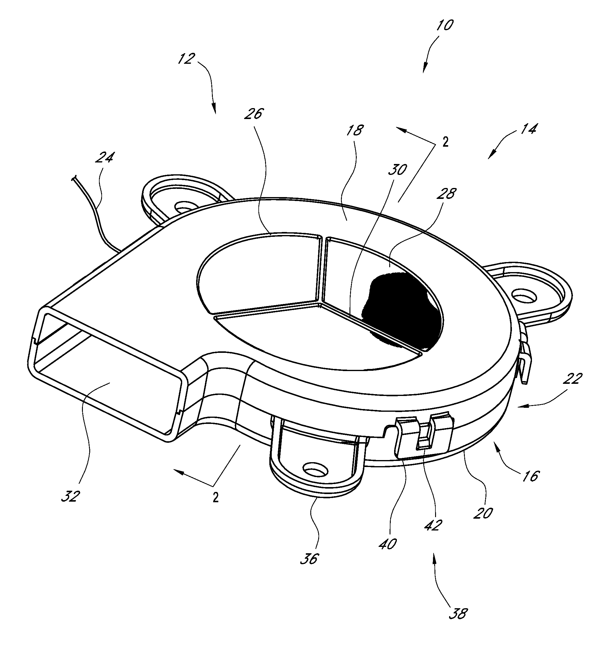
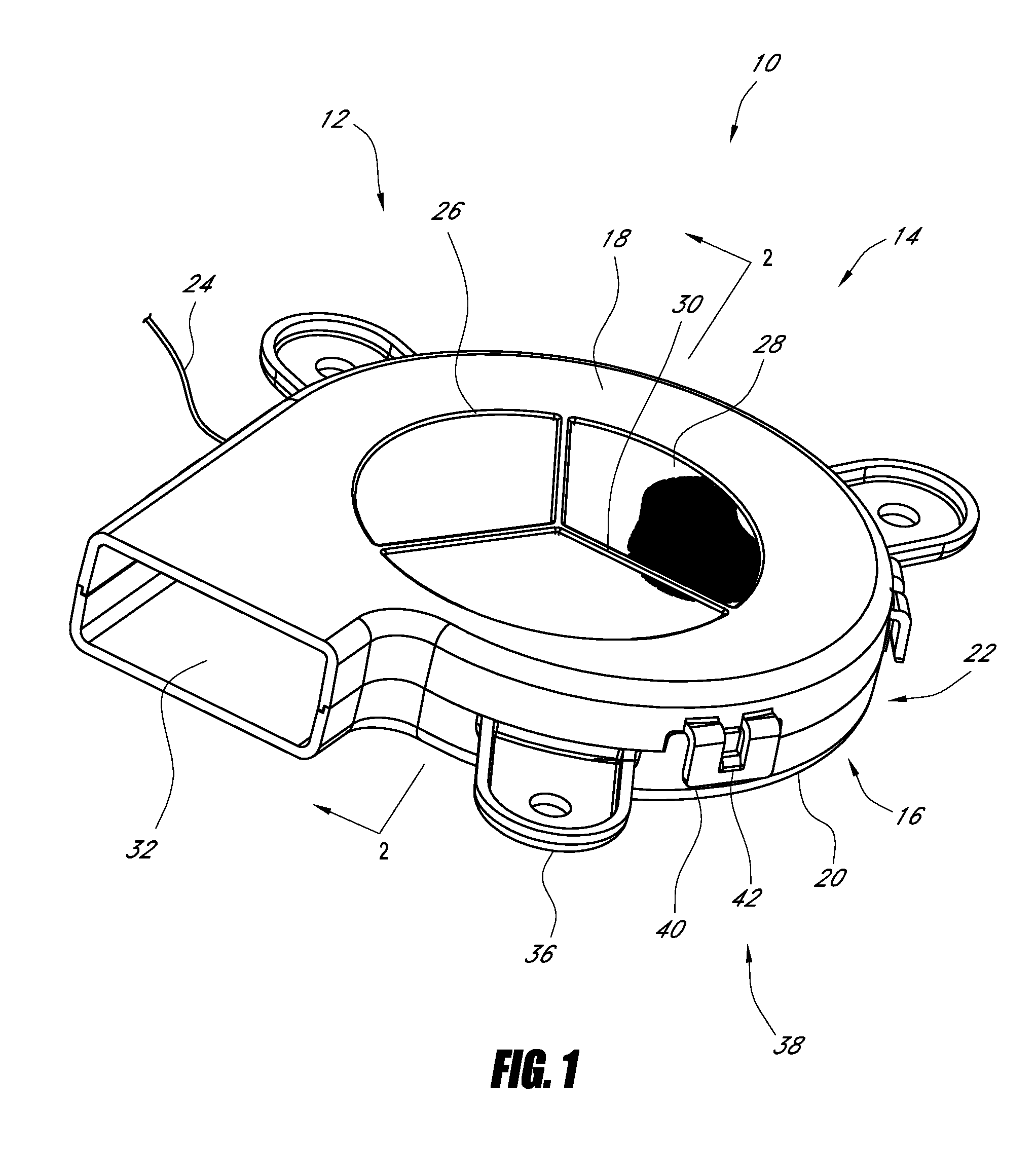
[0009]Several variations and/or combinations of an improved blower are disclosed. In various embodiments, the blower has a low-profile (e.g., reduced axial thickness) configuration. Some embodiments have an integrated filter configured to inhibit contaminants from entering the blower. In certain embodiments, the blower has impeller blades having a reduced thickness, which can reduce noise and/or turbulence. Moreover, certain embodiments have a wire channel configured to route wires therethough, which can reduce the axial thickness of the blower. In some embodiments, the blower has an exposed backplate, thereby enhancing the heat transfer between the blower and the surrounding environment. The blower can include a circuit board on which the electronic components are arranged at least partly on their height. In some embodiments, the blower has a motor base configured to reduce the axial thickness of t
Problems solved by technology
In many instances, the amount of space available within, below, and around the seat for such ventilation and/or temperature control systems is severely limited.
Certain conventional ventilation and/or temperature control systems are too large to be mounted within, below, or around vehicle seats.
Such systems are bulky and difficult to
Method used
View moreImage
Smart ImageViewing Examples
Examples
 PUM
 Abstract
A blower configured to be positioned in confined spaces and to provide ventilation of a fluid, such as temperature controlled air, is disclosed. In various embodiments, the blower is configured to have a reduced axial thickness, which can be desired in such confined spaces. In some embodiments, the blower has an integral filter, a wire channel for the routing of one or more wires, and/or an exposed backplate. In some embodiments, the blower has a snap-fit circuit board, containment system for mounting the motor, one or more vanes for directing fluid flow, shrouded impeller, and/or integrated connector.
Description
CROSS-REFERENCE TO RELATED APPLICATIONS[0001]This application claims the priority benefit under 35 U.S.C. §119(e) of U.S. Provisional Application No. 61 / 410,823, filed Nov. 5, 2010, and U.S. Provisional Application No. 61 / 483,590, filed May 6, 2011, the entirety of each of which is hereby incorporated by reference.BACKGROUND[0002]1. Field[0003]The present application relates generally to ventilation devices. More particularly, some embodiments relate to a blower that is particularly useful for providing a flow of temperature-controlled air in confined spaces, such as seats (e.g., vehicle seats, wheelchair seats, and other seating assemblies), beds, and other occupant support assemblies.[0004]2. Description of the Related Art[0005]Certain modern seats, such as some automobile seats, are equipped with ventilation systems that supply air to, or receive air from, a portion of the seat. Some such seats also include temperature control systems that allow the occupant to vary the temperatu...
Claims
Login to View More Application Information
Patent Timeline
 IPC IPC(8): F04D1/00
CPCF04D29/4226F04D25/0693F04D25/068F04D29/703F04D17/08F04D25/08F04D29/281F04D29/4206F04D29/663
Inventor LOFY, JOHNWALSH, RYAN
Owner GENTHERM INC
Features
- R&D
- Intellectual Property
- Life Sciences
- Materials
- Tech Scout
- Unparalleled Data Quality
- Higher Quality Content
- 60% Fewer Hallucinations
Learn More Browse by: Latest US Patents, China's latest patents, Technical Efficacy Thesaurus, Application Domain, Technology Topic, Popular Technical Reports.
© 2025 PatSnap. All rights reserved.Legal|Privacy policy|Modern Slavery Act Transparency Statement|Sitemap|About US| Contact US: help@patsnap.com


