
Blind-spot image display system for vehicle, and blind-spot image display method for vehicle

a technology of blind spot image and display system, which is applied in the field of blind spot image display system for vehicle and blind spot image display method for vehicle, can solve problems such as inconsistency, and achieve the effect of easy understanding and contributing to the implementation of safe driving

Active Publication Date: 2012-05-10
CLARION CO LTD
View PDF2 Cites 41 Cited by
  • Summary
  • Abstract
  • Description
  • Claims
  • Application Information

AI Technical Summary

Benefits of technology

The present invention provides a system for displaying semi-see-through images in a vehicle, which can be easily understood by users. The system uses a stabilization period to gradually show the image, and combines the vehicle cabin image with other camera images to create a more realistic and easy-to-understand view. The system also includes an animation image to explain the process and improve understanding. The system can be used in a see-through blind-spot image display system for vehicles, and can be enhanced through the use of an audio explanation function. The system is designed to be easily understood by users and contribute to safe driving.

Problems solved by technology

On the other hand, an inexperienced driver or a driver who needs to respond instantly may not keep the consistency between the image on the screen and the image viewed from the driver's seat, and thus feels a sense of inconsistency.

Method used


Image

  • Blind-spot image display system for vehicle, and blind-spot image display method for vehicle
  • Blind-spot image display system for vehicle, and blind-spot image display method for vehicle
  • Blind-spot image display system for vehicle, and blind-spot image display method for vehicle

Examples


embodiment 1

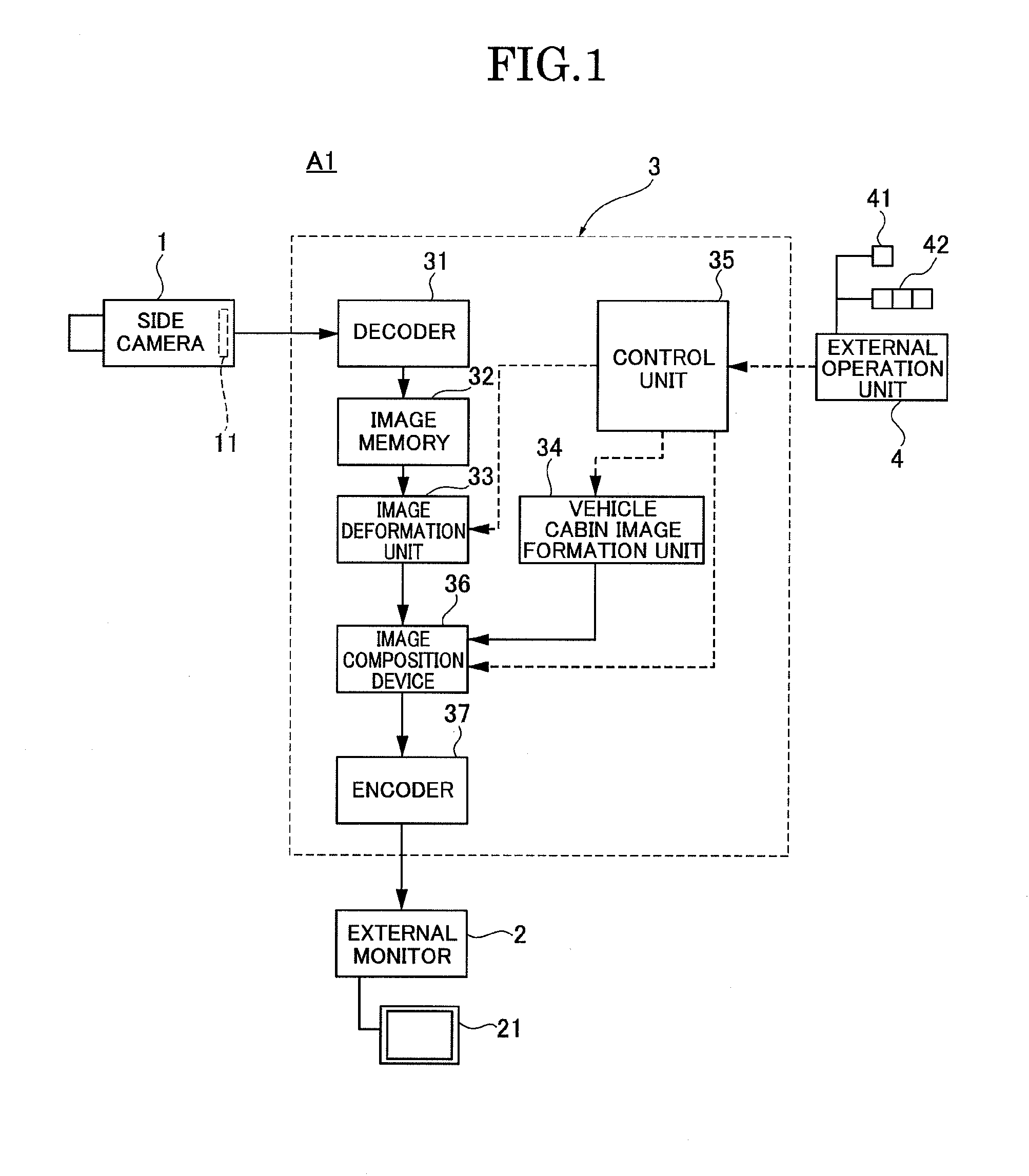
[0047]First, the configuration is described. FIG. 1 is an overall system block diagram showing a see-through side view monitor system A1 in Embodiment 1 (an example of a blind-spot image display system for vehicle).

[0048]The see-through side view monitor system A1 in Embodiment 1 is an example which employs, as an image processing technique for animation presentation, a semi-see-through technique which superimposes a vehicle cabin image with a transparency being changed stepwise, on the blind-spot image based on a real camera image signal (the semi-see-through technique is an image composition technique which superimposes a single sheet of a vehicle cabin image with a transparency being changed stepwise, on the original blind-spot image, and thus hereinafter, referred to as a single layer semi-see-through technique). As shown in FIG. 1, the system A1 includes a side camera 1 (camera), an external monitor 2 (monitor), an image processing control unit 3 (image processing controller), ...

embodiment 2

[0107]Embodiment 2 is an example in which at the time of animation display, a blind-spot image acquired by reading pre-stored information is used instead of the blind-spot image from the camera image.

[0108]First, the configuration is described. FIG. 4 is an overall system block diagram showing a see-through side view monitor system A1 in Embodiment 2 (an example of a blind-spot image display system for vehicle).

[0109]The see-through side view monitor system A2 in Embodiment 2 is an example which employs, as an image processing technique for animation presentation, a single layer semi-see-through technique which superimposes a vehicle cabin image with a transparency being changed stepwise, on the blind-spot image based on memory information. As shown in FIG. 4, the system A2 includes a side camera 1 (camera), an external monitor 2 (monitor), an image processing control unit 3 (image processing controller), and an external operation unit 4.

[0110]As shown in FIG. 4, the image processin...

embodiment 3

[0128]In contrast to embodiments 1 and 2 which each employ the single layer semi-see-through technique, Embodiment 3 is an example which employs a planar layer semi-see-through technique for animation presentation.

[0129]First, the configuration is described. FIG. 6 is an overall system block diagram showing a see-through side view monitor system A3 in Embodiment 3 (an example of a blind-spot image display system for vehicle).

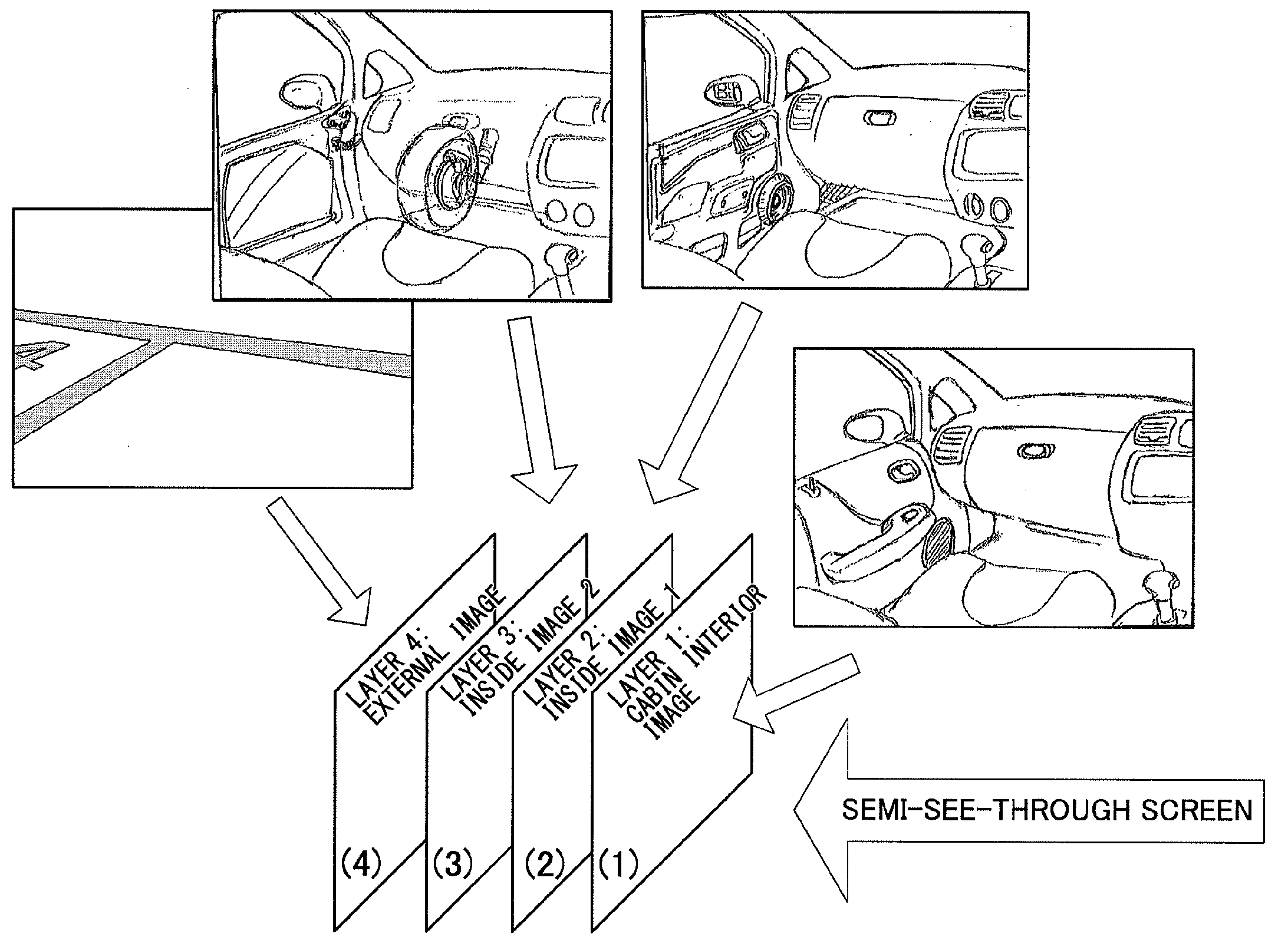
[0130]The see-through side view monitor system A3 in Embodiment 3 is an example which employs, as an image processing technique for animation presentation, a semi-see-through technique which has a plurality of layers in a stepwise exploded structure, and presents animation with a transparency being changed per layer (the semi-see-through technique is an image composition technique which superimposes multiple sheets of a vehicle cabin image with their transparencies being changed stepwise, on the original blind-spot image, and thus hereinafter, referred to as a m...


PUM


Abstract

A see-through side view monitor system (A1) including a camera (1), an external monitor (2), and an image processing controller (3) having an image deformation unit (33) configured to perform point-of-view conversion on a real camera image signal inputted from the camera into a blind-spot image that is viewed from the position of the driver's point of view, a vehicle cabin image formation unit (34) configured to form a vehicle cabin image that is viewed from the position of the driver's point of view, an image composition device (36) configured to generate a transparent display image showing a blind-spot image transmitted through a semi-see-through vehicle cabin image, and an image composition device (36) configured to generate an animation display image showing the blind-spot image to be shifted stepwise from the vehicle cabin image.

Description

TECHNICAL FIELD[0001]The present invention relates to a blind-spot image display system for vehicle and a blind-spot image display method for vehicle, with which a blind-spot image is displayed on a monitor as if the blind-spot image is an image of the blind spot seen from a position of a driver's point of view through a semi-transparent image of a vehicle cabin.BACKGROUND ART[0002]In the side view monitor system which is in practical use at present, a side camera (such as a CCD camera) is set inside a side mirror, and a real camera image from the side camera is displayed on a monitor screen of a front display unit which is also used for a navigation system.[0003]That is to say, displaying the front lateral area of a vehicle, which is the blind spot of a driver, on the monitor screen allows the driver to recognize the condition of the blind spot.[0004]However, because the side camera is disposed inside the side mirror, there is a high parallax (in a range of 1 m to 2 m) between the ...

Claims


Application Information

Patent Timeline
Patent Type & Authority Applications(United States)
IPC IPC(8): H04N7/18
CPCB60R1/00B60R2300/202B60R2300/304B60R2300/60H04N7/18G06T3/4038G06T11/00G06T19/00G06T19/006B60R2300/8026B60R1/25
Inventor SATOH, NORIYUKI
Owner CLARION CO LTD
Learn More