
Methods and apparatus for displacing fluids from substrates using supercritical co2

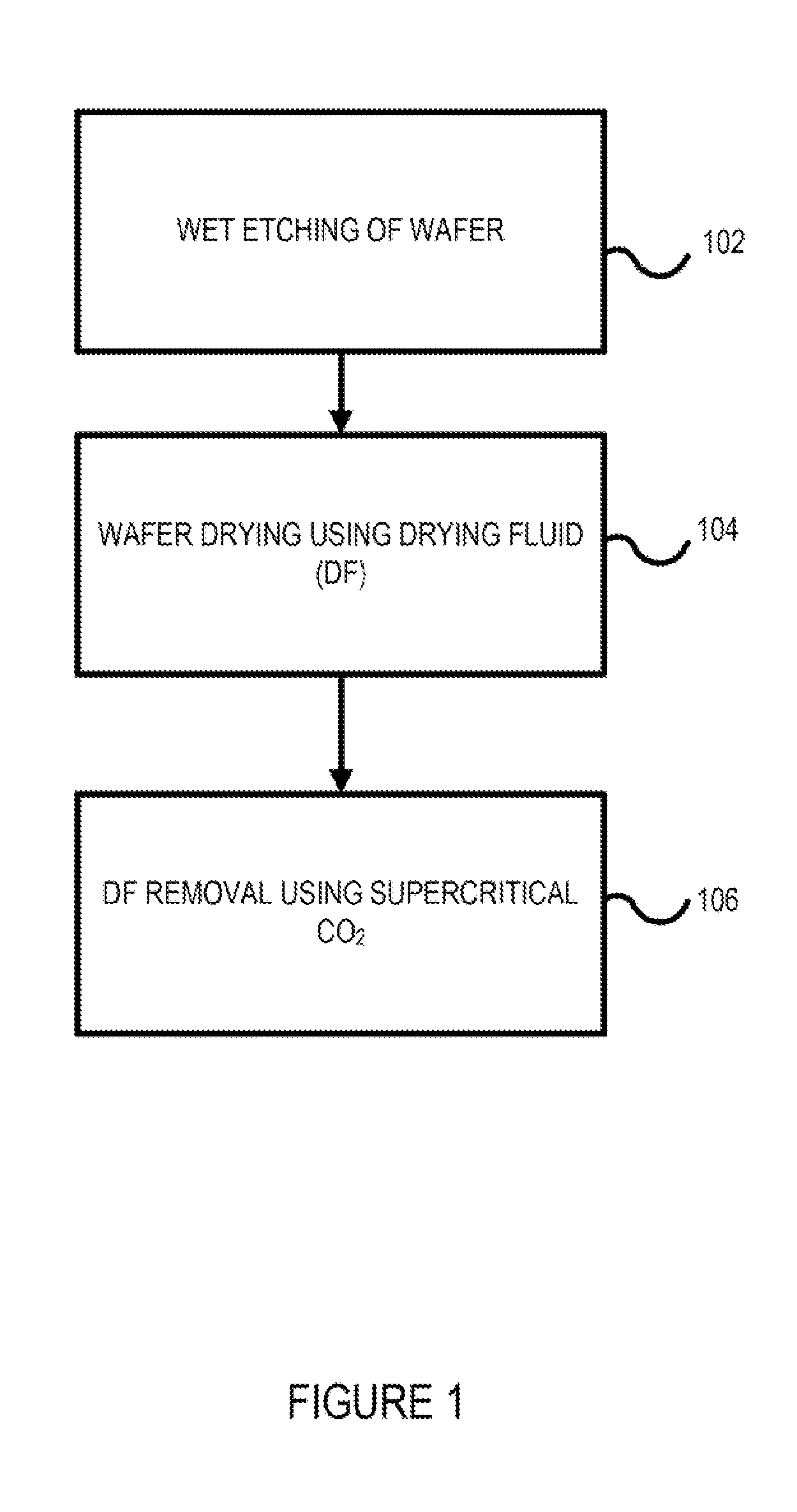
a technology of supercritical co2 and fluids, which is applied in the direction of cleaning processes and apparatus, cleaning using liquids, and polishing/cleaning of conductive patterns, etc., can solve the problems of increasing the total process time and volume of co2 required, requiring a long time for df agents and any other remaining residues to be satisfactorily removed, and requiring a large amount of tim

Active Publication Date: 2012-05-10
LAM RES CORP
View PDF0 Cites 8 Cited by
  • Summary
  • Abstract
  • Description
  • Claims
  • Application Information

AI Technical Summary

Problems solved by technology

Existing DF removal processes utilizing supercritical CO2 have shown promising results toward preventing collapse of fragile structures, but often been time consuming, requiring a long time for DF agents and any other remaining residues to be satisfactorily removed.
Existing DF removal processes using supercritical CO2 also require a large number of chamber turnovers to satisfactorily flush DF agents and any other remaining residues from the substrate surface, thereby undesirably increasing the total process time and volume of CO2 required, and reducing manufacturing productivity.

Method used


Image

  • Methods and apparatus for displacing fluids from substrates using supercritical co2
  • Methods and apparatus for displacing fluids from substrates using supercritical co2
  • Methods and apparatus for displacing fluids from substrates using supercritical co2

Examples


Embodiment Construction

[0012]The present invention will now be described in detail with reference to a few embodiments thereof as illustrated in the accompanying drawings. In the following description, numerous specific details are set forth in order to provide a thorough understanding of the present invention. Many of the descriptions are relevant to a mini-batch drying process, in which multiple wafers are stacked above each other in the pressure chamber, but the principles described are applicable to a single wafer process as well. It will be apparent, however, to one skilled in the art, that the present invention may be practiced without some or all of these specific details. In other instances, well known process steps and / or structures have not been described in detail in order to not unnecessarily obscure the present invention.

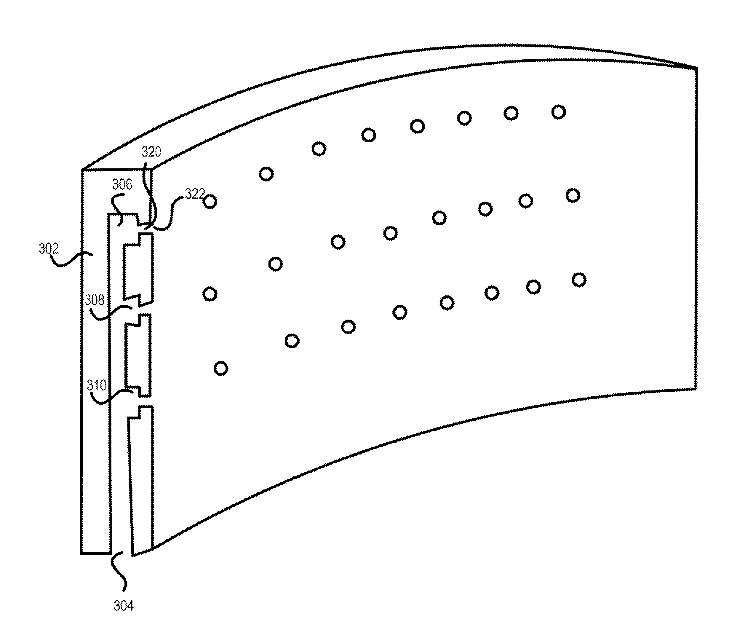
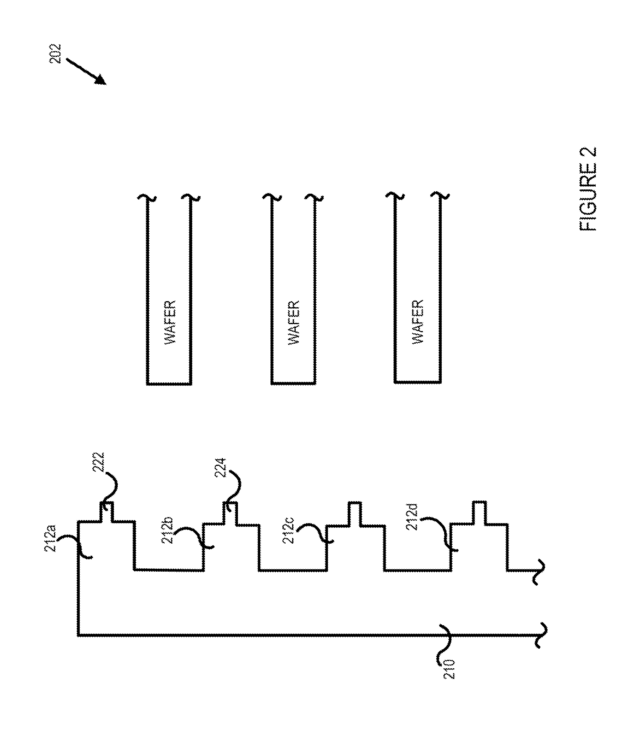
[0013]The invention relates, in one or more embodiment, to an innovative substrate processing chamber design that employs either a plurality of nozzles or slits arranged such...


PUM


Abstract

A processing chamber for post-wet-etch removing of drying fluid (DF) is disclosed. The chamber includes a chamber wall surrounding a processing volume and a plurality of nozzles disposed annularly about the processing volume and arranged into a set of nozzle rows that includes at least one nozzle row. The chamber also includes a plenum and a set of manifolds coupled to the plurality of nozzles to deliver the supercritical CO2 to the plurality of nozzles. Each nozzle has a nozzle outlet directed toward an interior portion of the processing volume and the nozzles are configured to flow the supercritical CO2 toward the substrates in a manner that minimizes recirculation loops and vortices.

Description

BACKGROUND OF THE INVENTION[0001]The production of semiconductor products often requires wet etching or some other form of wet processing of substrates that involves exposing the substrates to an aqueous-based liquid. After wet processing, the processing fluid and / or any aqueous-based rinsing fluid that remains on the surface of the substrate typically needs to be removed in order to prepare the substrate for the next processing step.[0002]Generally speaking, the wet processing fluid and / or rinsing fluid may be removed by saturating the substrate with a drying fluid (DF) to displace the wet processing fluid. The drying fluid may be alcohol-based, for example, and may include surfactants and / or other adjuncts to maximize displacement efficiency. In order to avoid collapse of fragile structures on the substrate due to capillary forces, additional post-wet-processing step(s) may be performed to dry the substrate in a satisfactory manner[0003]As semiconductor features become smaller and...

Claims


Application Information

Patent Timeline
Patent Type & Authority Applications(United States)
IPC IPC(8): B08B3/00
CPCB08B7/0021H01L21/6719H01L21/67051H01L21/02101H01L21/302H01L21/3065H05K3/26
Inventor NIXON, RONDA K.SHAREEF, IQBAL A.WAGNER, MARK I.MCANDREW, ROBERTKROEKER, TONY RAY
Owner LAM RES CORP
Learn More