
Replacement system for a surgical wire

a replacement system and wire technology, applied in the field of surgical wire replacement systems, can solve the problems of more time in the operating room, wire breakage, wire fracture,

Inactive Publication Date: 2012-05-03
ACUTE INNOVATIONS
View PDF10 Cites 22 Cited by
  • Summary
  • Abstract
  • Description
  • Claims
  • Application Information

AI Technical Summary

Benefits of technology

[0005]Each wire may be pre-attached to a curved needle that is used to guide the wire around (or through) each sternal half. Generally, all of the wires are positioned around the sternal halves while the halves are spaced from one another (i.e., while the chest cavity is open), which simplifies wire placement, allows use of a shorter needle, and minimizes the chance of piercing the heart with the needle.
[0007]A disadvantage of this low-tech approach for sternal closure is breakage of the wire: twisting the wire ends may fracture the wire. Once a wire breaks, the surgeon may choose to re-open the chest cavity, to allow a replacement wire to be placed around the sternum with less risk of heart puncture. Accordingly, if other wires already have been secured around the sternum, the surgeon removes and replaces these other wires, too. The net result can be more time in the operating room, increased risk to the patient, and frustration for the surgeon.

Problems solved by technology

A disadvantage of this low-tech approach for sternal closure is breakage of the wire: twisting the wire ends may fracture the wire.
The net result can be more time in the operating room, increased risk to the patient, and frustration for the surgeon.

Method used


Image

  • Replacement system for a surgical wire
  • Replacement system for a surgical wire
  • Replacement system for a surgical wire

Examples


Embodiment Construction

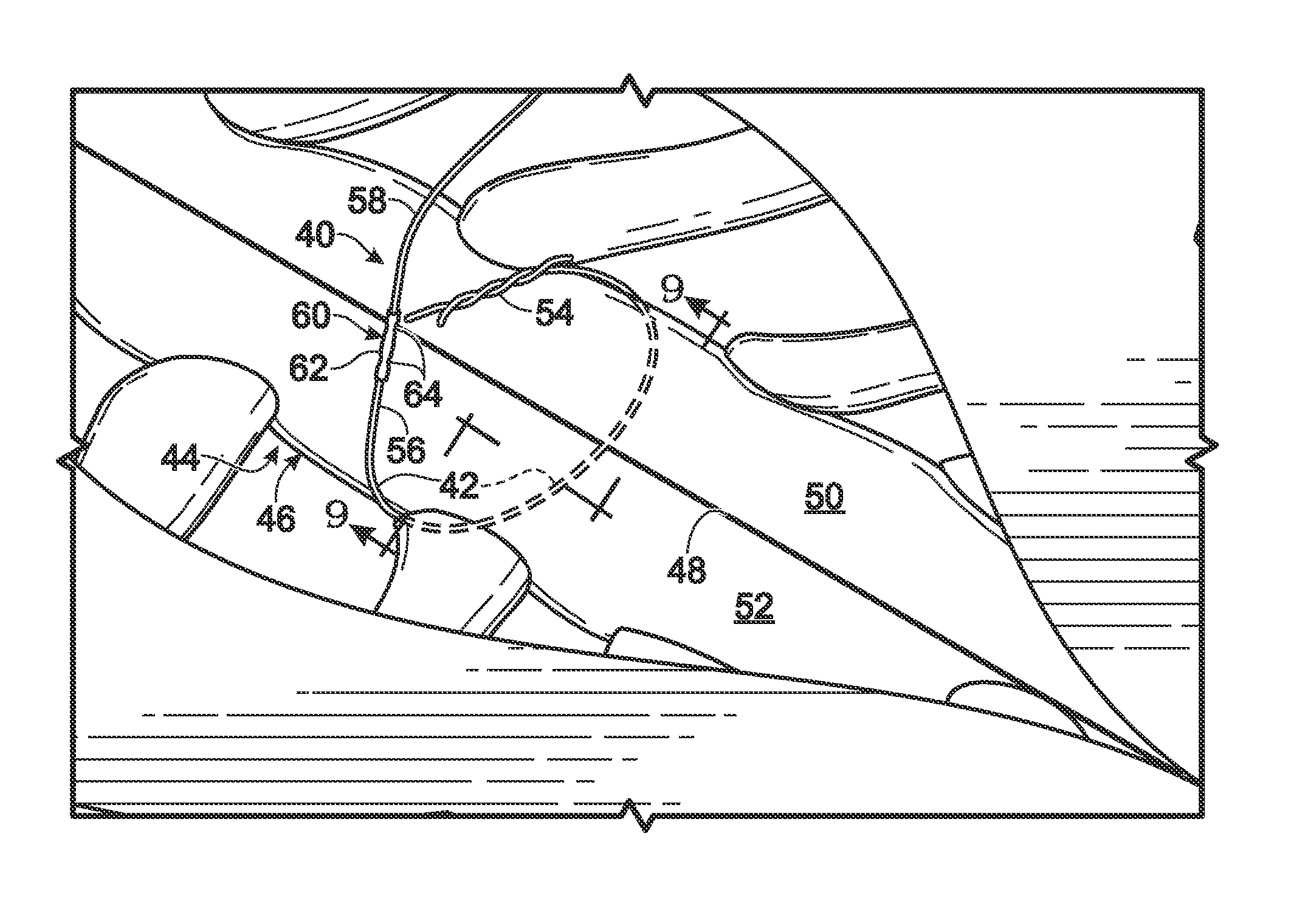
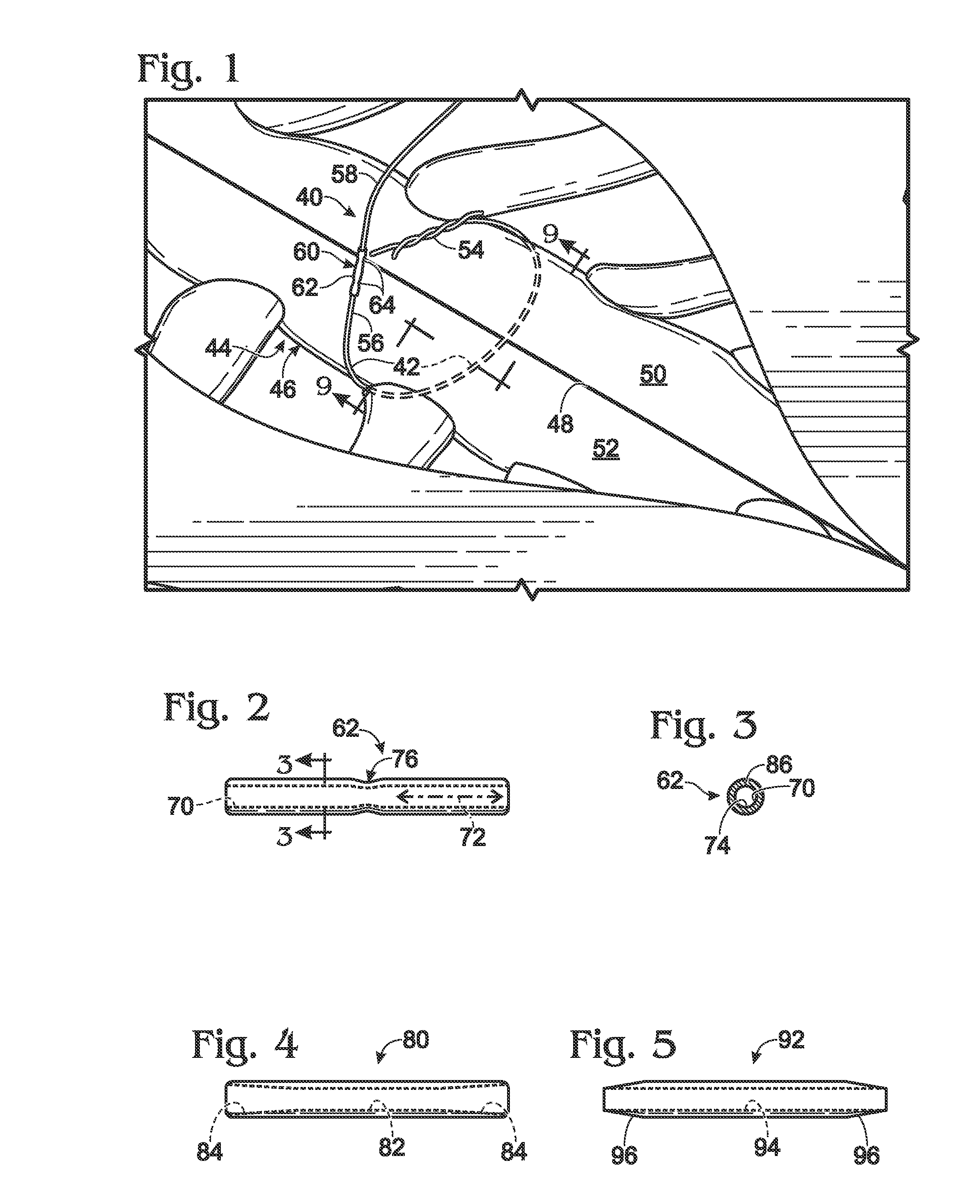
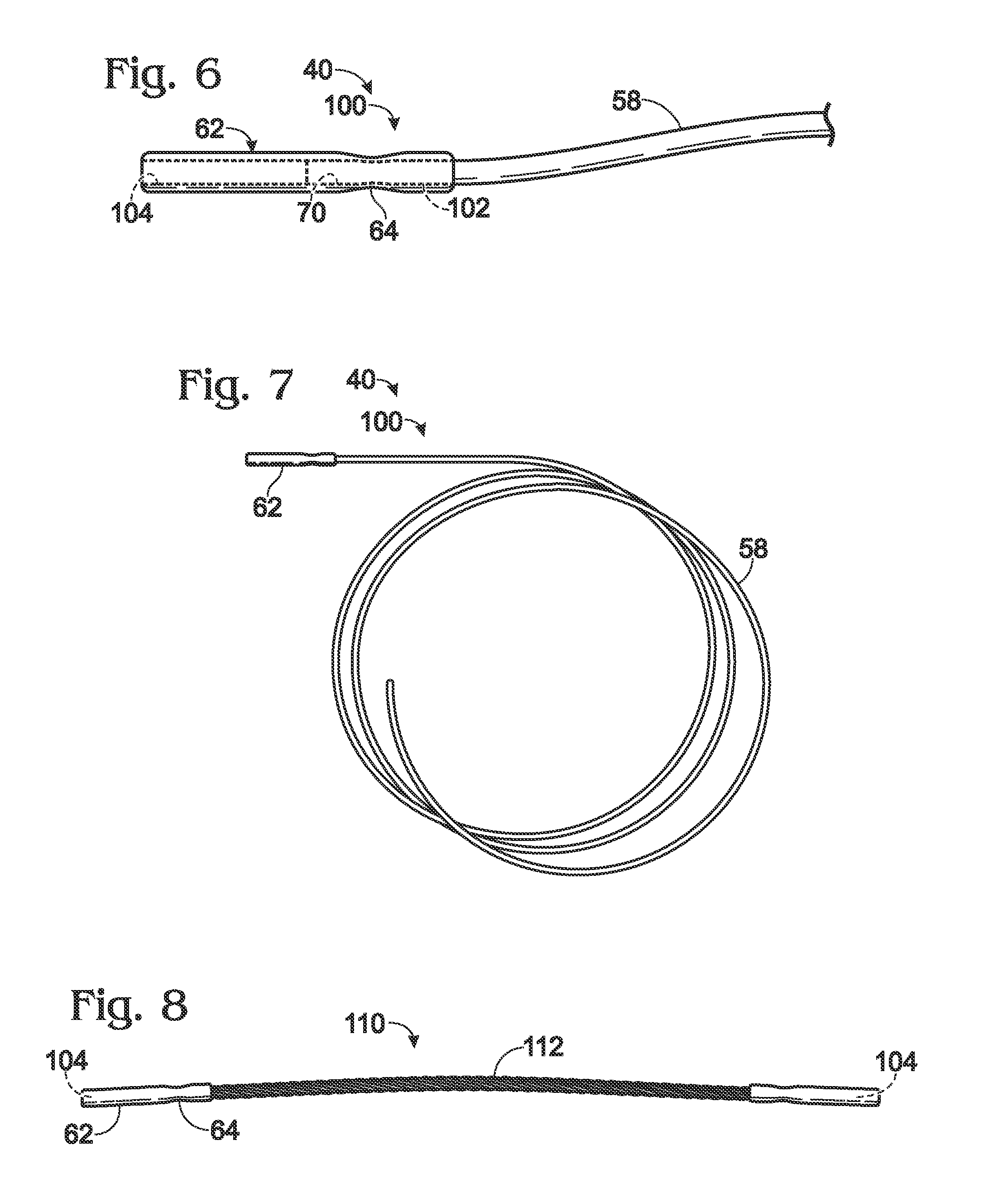
[0029]The present disclosure provides a system, including methods, apparatus, and kits, for replacing a damaged surgical wire, such as a surgical wire that has broken during installation as a suture (a fixation loop) for bone. The system may include a connector with at least one ferrule for attaching a substitute wire to a damaged wire, and provides a method of replacing a damaged wire with a substitute wire by using the damaged wire as a leader for travel of the substitute wire around bone.

[0030]The connector may include at least one ferrule forming at least one receptacle capable of receiving an end of a surgical wire, namely, a damaged wire, a substitute wire, or both interchangeably. The ferrule may be attached to the wire end, to secure the end of the wire to the ferrule. The ferrule may be attached by any suitable mechanism, such as deformation of the ferrule and / or wire, use of an adhesive, bonding, application of axial tension to the wire and ferrule (with a woven ferrule), ...


PUM


Abstract

System, including methods, apparatus, and kits, for replacing a damaged surgical wire, such as a surgical wire that has broken during or after installation around bone. The system may include a connector with at least one ferrule for attaching a substitute wire to a damaged wire and provides a method of replacing a damaged wire with a substitute wire by using the damaged wire as a leader for travel of the substitute wire around bone.

Description

CROSS-REFERENCE TO PRIORITY APPLICATION[0001]This application is based upon and claims the benefit under 35 U.S.C. §119(e) of U.S. Provisional Patent Application Ser. No. 61 / 409,415, filed Nov. 2, 2010, which is incorporated herein by reference in its entirety for all purposes.INTRODUCTION[0002]The rib cage, or thoracic cage, is composed of bone and cartilage that surround the chest cavity and organs therein, such as the heart and the lungs. In humans, the rib cage typically consists of 24 ribs, twelve thoracic vertebrae, the sternum (or breastbone), and the costal cartilages. The ribs articulate with the thoracic vertebrae posteriorly and, with the exception of the bottom two pairs of ribs (the floating ribs), are connected to the sternum anteriorly by the costal cartilages.[0003]Major surgery inside the chest cavity, such as open heart surgery, generally requires that the rib cage be opened. The most common procedure for opening the rib cage is for a surgeon to place a longitudina...

Claims


Application Information

Patent Timeline
Patent Type & Authority Applications(United States)
IPC IPC(8): A61B17/82
CPCA61B17/82A61B17/823A61B17/8861
Inventor BERNSTEIN, OREN S.
Owner ACUTE INNOVATIONS
Learn More