
Gyroplane prerotation by compressed air

a technology of compressed air and gyroplane, which is applied in the direction of rotorcraft, vehicles, aircrafts, etc., can solve the problems of reducing the lift generated by the advancing blade, disproportionate lifting, and limiting the maximum flight speed of fixed-wing aircraft, so as to improve the take-off performance and reduce the complexity. , the effect of improving the take-off performan

Inactive Publication Date: 2012-05-03
GROEN BROS AVIATION GLOBAL +1
View PDF15 Cites 12 Cited by
  • Summary
  • Abstract
  • Description
  • Claims
  • Application Information

AI Technical Summary

Benefits of technology

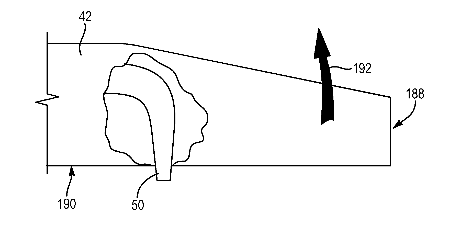
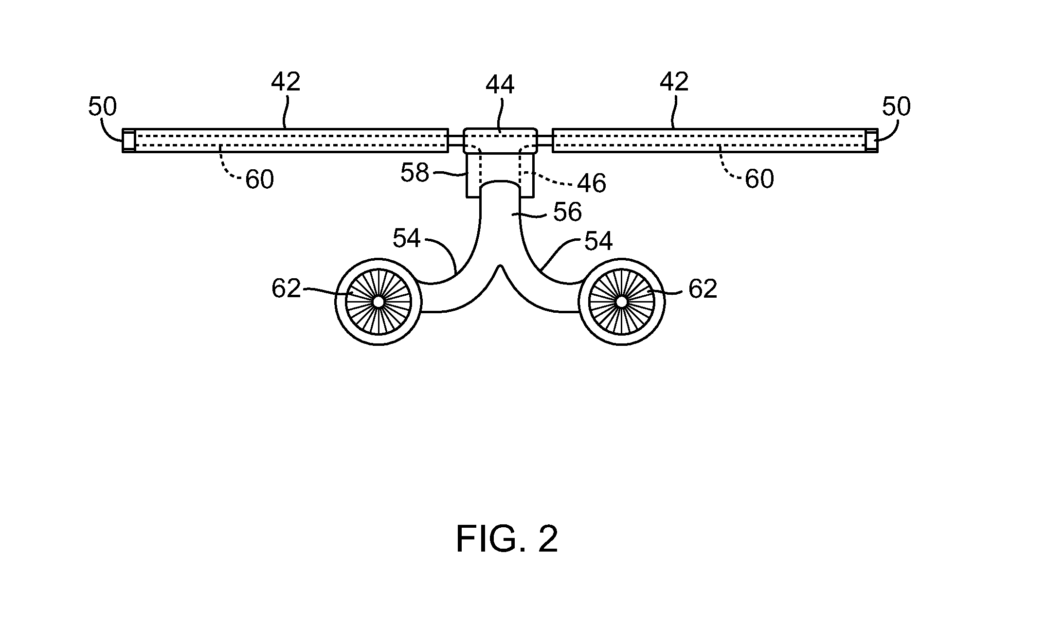
[0042]Rotorcraft utilizing one or more rotors prerotated by tip nozzles may generate substantially no torque between the rotor or rotors and the airframe. Accordingly, a compressed air prerotation system in accordance with the present invention may be utilized during take-off (e.g., after the aircraft is in flight). This may provide improved take-off performance.
[0043]Additionally, unlike current systems, rotorcraft in accordance with the present invention may not require complex and heavy transmissions and interconnecting drive shafts, hydraulic pumps, motors, or the like. Instead, they may typically include simple, light ducting. Accordingly, rotorcraft in accordance with the present invention may include a prerotation system that is less complex, easier to maintain, and lighter in weight.

Problems solved by technology

Although typical rotorcraft provide the significant advantage of vertical takeoff and landing (VTOL), they are much more limited in their maximum flight speed than are fixed-wing aircraft.
If left unchecked, this disproportionate lift may render the rotorcraft unflyable.
This, in turn, reduces the lift generated by the advancing blade.
This, in turn, increases the lift generated by the retreating blade.
However, lift equalization due to flapping is limited by retreating blade stall.
At certain higher speeds in the direction of flight, the increase in the blade angle of attack required to equalize lift results in loss of lift (stalling) of the retreating blade.
Accordingly, helicopters are quite limited in how fast they can fly.
In autogyro aircraft, the tips of the advancing blades are also subject to this increased drag, even for flight speeds much lower than the speed of sound.
Nevertheless, the same drag increase occurs eventually.
Electrical prerotation systems tend to be comparatively heavy and are mostly used on small “experimental” autogyro aircraft.

Method used


Image

  • Gyroplane prerotation by compressed air
  • Gyroplane prerotation by compressed air
  • Gyroplane prerotation by compressed air

Examples


Embodiment Construction

[0058]It will be readily understood that the components of the present invention, as generally described and illustrated in the drawings herein, could be arranged and designed in a wide variety of different configurations. Thus, the following more detailed description of the embodiments of the system and method of the present invention, as represented in the drawings, is not intended to limit the scope of the invention, as claimed, but is merely representative of various embodiments of the invention. The illustrated embodiments of the invention will be best understood by reference to the drawings, wherein like parts are designated by like numerals throughout.

[0059]Referring to FIG. 1, a rotorcraft 10 in accordance with the present invention may include an airframe 12 defining a cabin for carrying an operator, passengers, cargo, or the like. The airframe 12 may include one or more fixed wings 14 or airfoils 14 providing lift to the rotorcraft 10. The wings 14 may be configured such t...


PUM


Abstract

A rotorcraft is disclosed. The rotorcraft may include a rotor having at least one tip nozzle, a compressor having an outlet for compressed air, and a network of conduits connecting the outlet of the compressor with the tip nozzle. In operation, the compressor may deliver a flow of compressed air to the tip nozzle. As the flow of compressed air exits the at least one tip nozzle, it may cause rotation of the rotor. This rotation may prerotate the rotor and shorten the take off distance required by the rotorcraft. Take off of the rotorcraft may be accomplished without ever adding fuel to the flow of compressed air to the tip nozzle.

Description

RELATED APPLICATIONS [0001]This application claims the benefit of co-pending U.S. patent application Ser. No. 13 / 199,671, filed on Sep. 7, 2011, which claims the benefit of U.S. Provisional Patent Application Ser. No. 61 / 381,291, filed on Sep. 9, 2010, co-pending U.S. patent application Ser. No. 13 / 199,684, filed on Sep. 7, 2011, which claims the benefit of U.S. Provisional Patent Application Ser. No. 61 / 403,099, filed on Sep. 9, 2010, co-pending U.S. patent application Ser. No. 13 / 199,678, filed on Sep. 7, 2011, which claims the benefit of U.S. Provisional Patent Application Ser. No. 61 / 403,097, filed on Sep. 9, 2010, co-pending U.S. patent application Ser. No. 13 / 199,682, filed on Sep. 7, 2011, which claims the benefit of U.S. Provisional Patent Application Ser. No. 61 / 381,313, filed on Sep. 9, 2010, co-pending U.S. patent application Ser. No. 13 / 199,681, filed on Sep. 7, 2011, which claims the benefit of U.S. Provisional Patent Application Ser. No. 61 / 403,111, filed on Sep. 9, 20...

Claims


Application Information

Patent Timeline
IPC IPC(8): B64C27/02B64C27/00
CPCB64C27/025B64C2027/8245B64C27/82B64C2027/8254
Inventor VAN DER WESTHUIZEN, JACOB JOHANNES
Owner GROEN BROS AVIATION GLOBAL
Learn More