
Device for the production on-demand of hydrogen by electrolysis of aqueous solutions from dry cathode

a technology of dry cathode and electrolysis, which is applied in the direction of electrolysis process, electrolysis components, cells, etc., can solve the problems of affecting the industrialization of such devices, not being able to be coupled directly, and not allowing a defined physical separation of hydrogen and oxygen produced, etc., to achieve high purity

Active Publication Date: 2012-05-03
ENAPTER SRL
View PDF5 Cites 21 Cited by
  • Summary
  • Abstract
  • Description
  • Claims
  • Application Information

AI Technical Summary

Benefits of technology

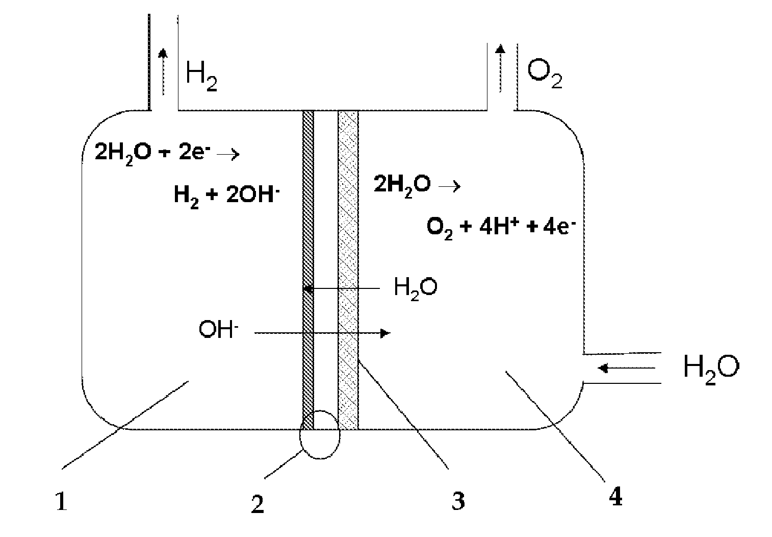
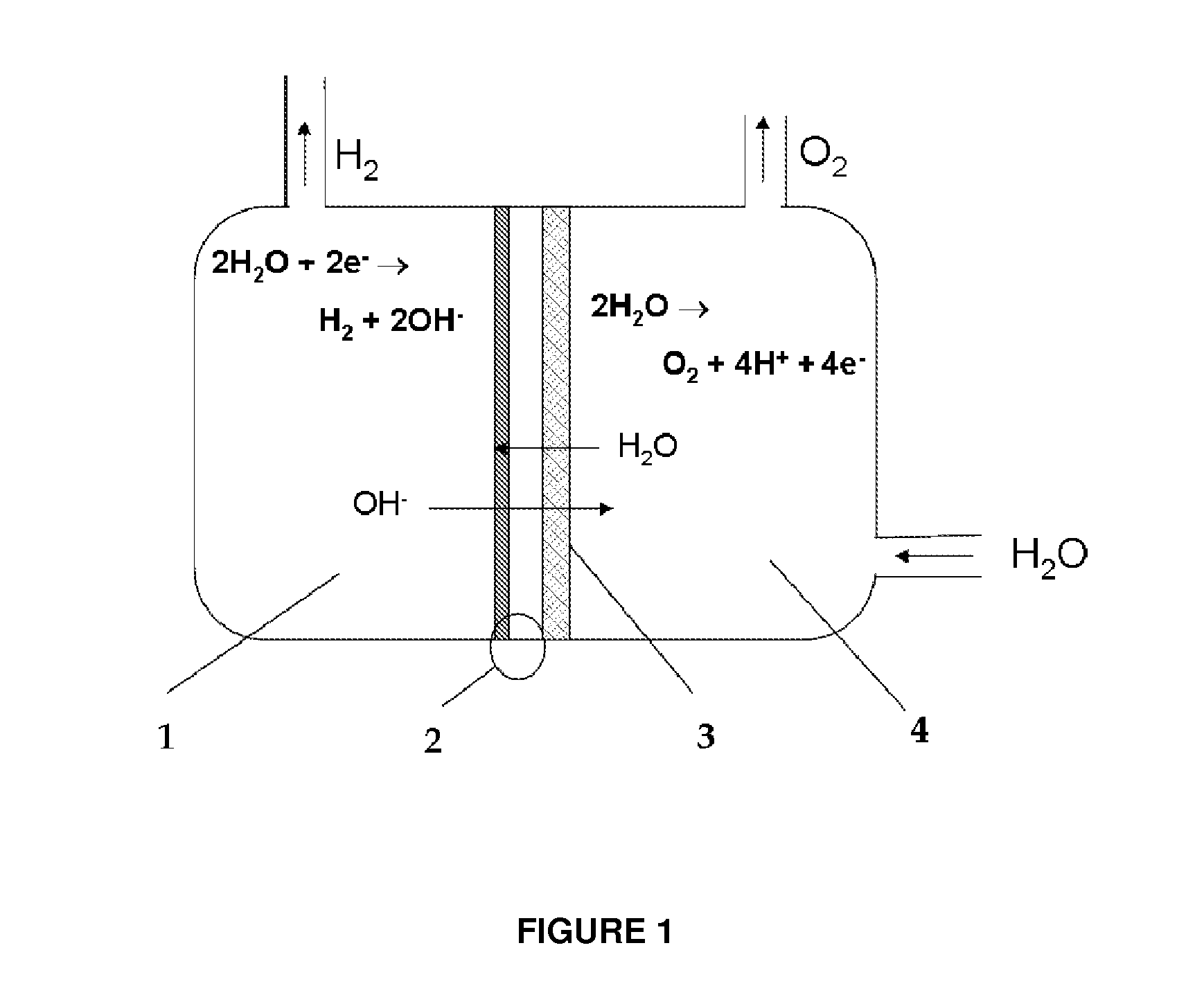
[0016]Such amount of water is adequate for the formation of hydrogen at a rate that allows only the electrolysis reaction without the evaporation of water. In this way the hydrogen produced has high purity (without any electrolytes) and is dry. The OH− ions formed during the cathodic half-reaction migrate through the membrane towards the other half-cell, ensuring the conditions for electrolytic equilibrium.

Problems solved by technology

Industrial scale electrolysers consist of two half-cells containing the electrodes (made by steel disks, for the simplest set-up), separated by a porous septum within circulates the electrolyte (alkali electrolysers usually use KOH) and which does not allow a defined physical separation of the hydrogen and the oxygen produced.
Consequently, this type of electrolysers is usually used to produce hydrogen at a pressure not higher than 7 bar with power supply connected to the grid and is not suitable to be coupled directly to renewable energy sources, inherently discontinuous.
The spread of such devices on an industrial scale is hindered by the scarcity and the high cost of the materials used for the membrane-electrode assembly.

Method used


Image

  • Device for the production on-demand of hydrogen by electrolysis of aqueous solutions from dry cathode
  • Device for the production on-demand of hydrogen by electrolysis of aqueous solutions from dry cathode

Examples


example 1

Production of the Anodic Electrode

[0038]4.5 g of CuSO4.5H2O and 10 g of CoCl2.6H2O were dissolved in 200 mL of distilled water. This solution was added to a solution of 12 g of Na2CO3 dissolved in 150 mL of distilled water. The precipitate formed was filtered and washed with water. The powder, after being dried in vacuum oven, was pyrolized at 400° C. for 5 hours in air. The mixture was mixed with Teflon 10 wt % in distilled water, in amount sufficient to obtain a spreadable paste. This paste was applied on a net of metallic nickel.

example 2

Production Membrane Cathode Electrode Assembly

[0039]An anion exchange membrane Acta M6 (prepared similarly to Example 1 of patent WO2009 / 007922, sample SBSF14) in circular shape of diameter 50 mm is pre-treated for 1 hour with a 1 M KOH solution to enable the exchange of the membrane to a hydroxylic form, and then fixed within a circular hollow mold with inner diameter of 48 mm and there sealed.

[0040]A solution made by 2 g NiSO4.6H2O, 2 g NaH2PO3, 5 g of sodium citrate dissolved in 100 mL of distilled water and then added with ammonium hydroxide to pH 10 is placed inside a mold cavity, in contact with one surface of the membrane. After 1.5 hours the solution is removed from the mold and the membrane is then rinsed three times with deionized water.

example 3

Device Assembling

[0041]One of the favorites assembly of cell is obtained placing in direct contact the assembled MEA 2, metalized only on cathode side (as described in Example 2), with the anode 3, made in accordance with Example 1. The anodic half-cell 4 is fed with an alkaline solution and the cathodic half-cell contains only the hydrogen produced by electrolysis process.


PUM

PropertyMeasurementUnit
Temperatureaaaaaaaaaa
Electric potential / voltageaaaaaaaaaa
Concentrationaaaaaaaaaa

Abstract

This invention relates to a device for the electrolytic production of hydrogen which can operate discontinuously or associated to strong power fluctuations and provide dry pressurized directly hydrogen, with high purity. The device for the electrolytic production of hydrogen from an alkaline aqueous solution, starting from dry cathode, comprises two half-cell, anodic and cathodic, separated by an anionic exchange membrane whose surface in contact with the cathodic half-cell is a membrane-electrode assembly (MEA), and the alkaline solution is present only in the anodic half-cell

Description

FIELD OF INVENTION[0001]The invention relates to the field of devices for the electrolytic production of hydrogen.STATE OF THE ART[0002]Hydrogen can be produced from multiple sources such as fossil fuels (by reforming reactions) or by electrolysis. Desiring to get it by means of electrolytic devices, one of the cheapest source of hydrogen is water.[0003]The electrolysis of water is, among the methodologies used to produce hydrogen, the one that allows to obtain high purity gases and, if the energy source for the electrolysis arises from renewable sources, low environmental impact. The half-reactions of water electrolysis are:2H2O+2e−→H2+2OH−  cathode2H2O→O2+4H++4e−  anodeFor the production of electrodes for the electrolysis reaction are generally used metals and alloys arranged in the form of nets or plates or, as alternative, may be used electrocatalysts made of one or more metals selected from noble metals (such as but not only Re, Ru, Rh, Os, Ir, Pt, Pd—Au, Cu, Ag) or non-noble (...

Claims


Application Information

Patent Timeline
IPC IPC(8): C25B1/02C25B9/18C25B9/08C25B9/19C25B9/23
CPCC25B1/02Y02E60/366C25B1/04Y02P20/133Y02E60/36C25B9/73C25B9/23
Inventor TAMPUCCI, ALESSANDROBERT, PAOLO
Owner ENAPTER SRL
Learn More