Acoustic signal processing apparatus
a signal processing and acoustic signal technology, applied in the direction of stereophonic circuit arrangements, transducer details, electrical transducers, etc., can solve the problems of inability to perform such preferred level control, the high frequency component of an acoustic signal becomes too loud, and the uniform frequency response does not always suit the characteristic of acoustic signals
- Summary
- Abstract
- Description
- Claims
- Application Information
AI Technical Summary
Benefits of technology
Problems solved by technology
Method used
Image
Examples
first embodiment
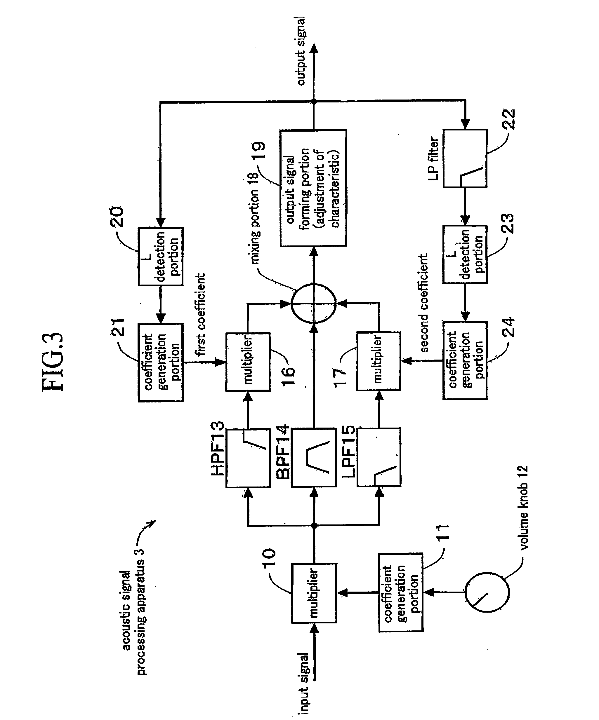
[0025]FIG. 3 indicates a circuit block diagram indicative of a configuration of the acoustic signal processing apparatus 3 of the present invention.
[0026]In the acoustic signal processing apparatus 3 shown in FIG. 3, an input acoustic signal is input to a multiplier 10 to multiply the input acoustic signal by a coefficient generated by a coefficient generation portion 11 which generates a coefficient corresponding to a rotation angle of a volume knob 12. By the multiplication, the full range volume level of the acoustic signal is controlled in accordance with the rotation angle of the volume knob 12. The acoustic signal output from the multiplier 10 and controlled to have the volume level corresponding to the volume knob is separated by a band separation filter group into a high frequency component, a middle frequency component and a low frequency component according to the band. The band separation filter group is formed of a high-pass filter (HPF) 13 for extracting a high frequenc...
second embodiment
[0031]FIG. 4 indicates a circuit block diagram indicative of a configuration of an acoustic signal processing apparatus 3-2 of the present invention. The sound system to which the acoustic signal processing apparatus 3-2 of the invention is to output signals has a multi-amp configuration formed of the plurality of speakers 5 corresponding to a plurality of bands and the plurality of power amplifiers 4 for individually driving the speakers, respectively. For the sake of simplifying explanation, FIG. 4 indicates an example of a 2-way speaker system. In this example, an acoustic signal is divided into high frequency and low frequency bands by a channel divider. As the power amplifiers 4, a power amplifier provided specifically for high frequency band and a power amplifier provided specifically for low frequency band are provided, while the 2-way speaker formed of a speaker for high frequency band (tweeter) and a speaker for low frequency band (woofer) is provided as the speakers 5. In ...
third embodiment
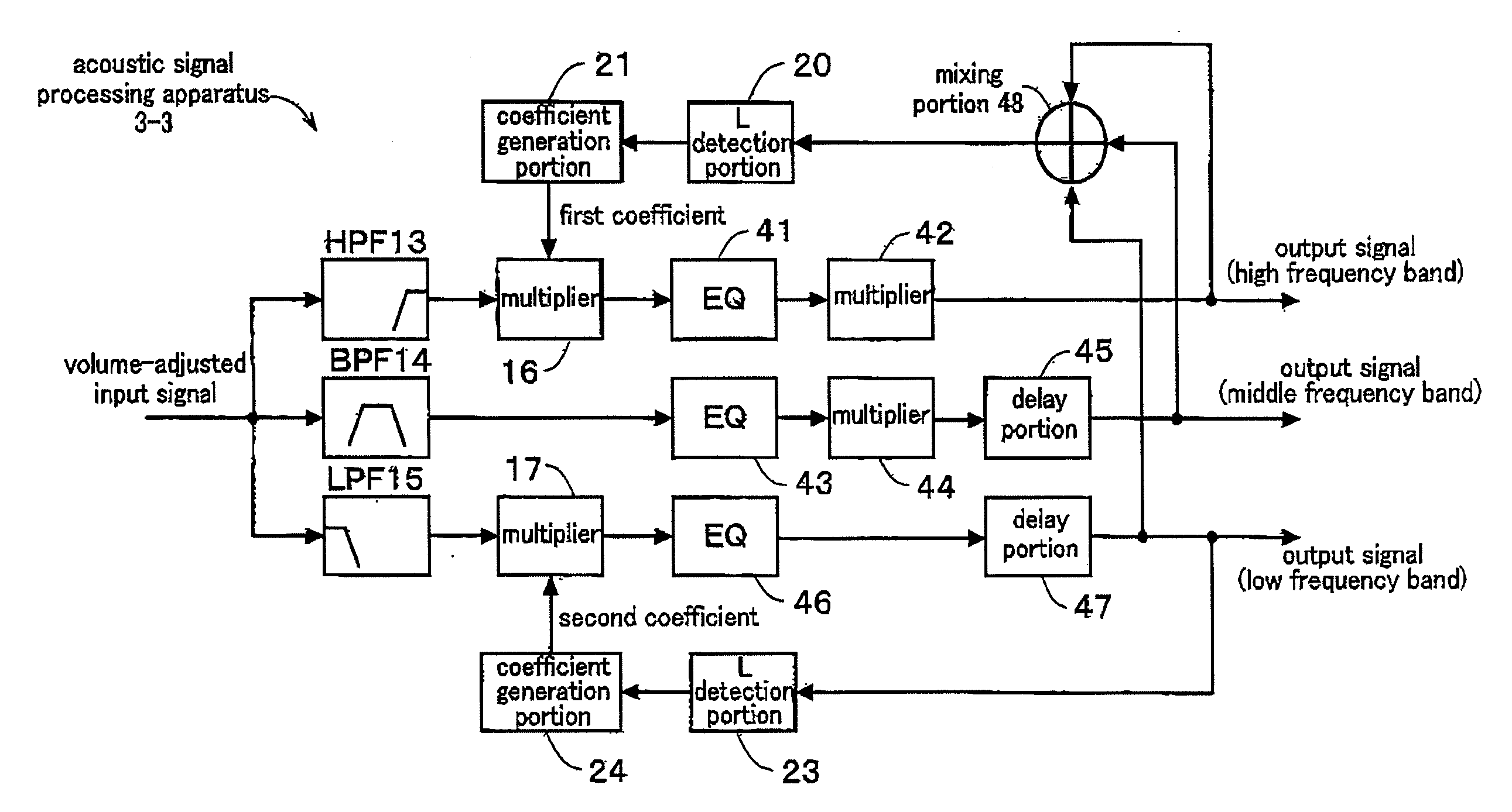
[0041]The high frequency component whose acoustic characteristic has been adjusted by the EQ 41 is supplied to a multiplier 42 to adjust the level of the high frequency component which is to be supplied to the high frequency speaker so that the level of a tone which is to be output from the high frequency speaker will be balanced with the level of a tone which is to be output from the low frequency speaker. From the multiplier 42, an output signal of the high frequency component is output to be amplified by the power amplifier provided specifically for high frequencies to be supplied to the high frequency speaker (tweeter). The middle frequency component whose acoustic characteristic has been adjusted by the EQ 43 is supplied to a multiplier 44 to adjust the level of the middle frequency component which is to be supplied to the middle frequency speaker so that the level of a tone which is to be output from the middle frequency speaker will be balanced with the level of a tone which ...
PUM
 Abstract
Description
Claims
Application Information
 - R&D
- Intellectual Property
- Life Sciences
- Materials
- Tech Scout
- Unparalleled Data Quality
- Higher Quality Content
- 60% Fewer Hallucinations
Browse by: Latest US Patents, China's latest patents, Technical Efficacy Thesaurus, Application Domain, Technology Topic, Popular Technical Reports.
© 2025 PatSnap. All rights reserved.Legal|Privacy policy|Modern Slavery Act Transparency Statement|Sitemap|About US| Contact US: help@patsnap.com


