
Inserter Device

a technology of inserting device and insertion needle, which is applied in the direction of trocar, other medical devices, infusion needles, etc., can solve the problems of limited shelf life and achieve the effect of limited shelf li

Inactive Publication Date: 2012-04-19
UNOMEDICAL AS
View PDF2 Cites 24 Cited by
  • Summary
  • Abstract
  • Description
  • Claims
  • Application Information

AI Technical Summary

Benefits of technology

[0013]The insertion device of claim 1 is provided with means for biasing the primary spring which primary spring might either provide insertion or retraction of the insertion needle. That the spring is only biased upon use makes it possible to e.g. use plastic springs as these springs have a limited shelf life when they are biased. Also, it is not necessary to provide the insertion device of claim 1 with any means preventing misfiring as misfiring cannot take place before the spring has been biased or loaded. The cover actually covers the insertion needle both along the sides of the insertion needle which prevents the patient from observing the insertion needle before and after insertion, also the cover covers the end of the needle in such a way that the cover is provided with an opening at the end surface which is placed against the patients skin through which opening the insertion needle might pass through but the opening is too narrow to let a finger pass through the opening.

Problems solved by technology

That the spring is only biased upon use makes it possible to e.g. use plastic springs as these springs have a limited shelf life when they are biased.

Method used


Image

  • Inserter Device
  • Inserter Device
  • Inserter Device

Examples


first embodiment

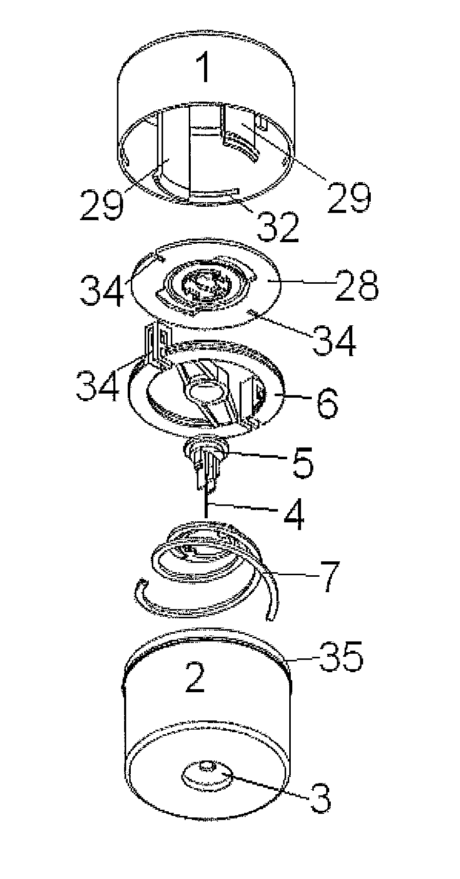
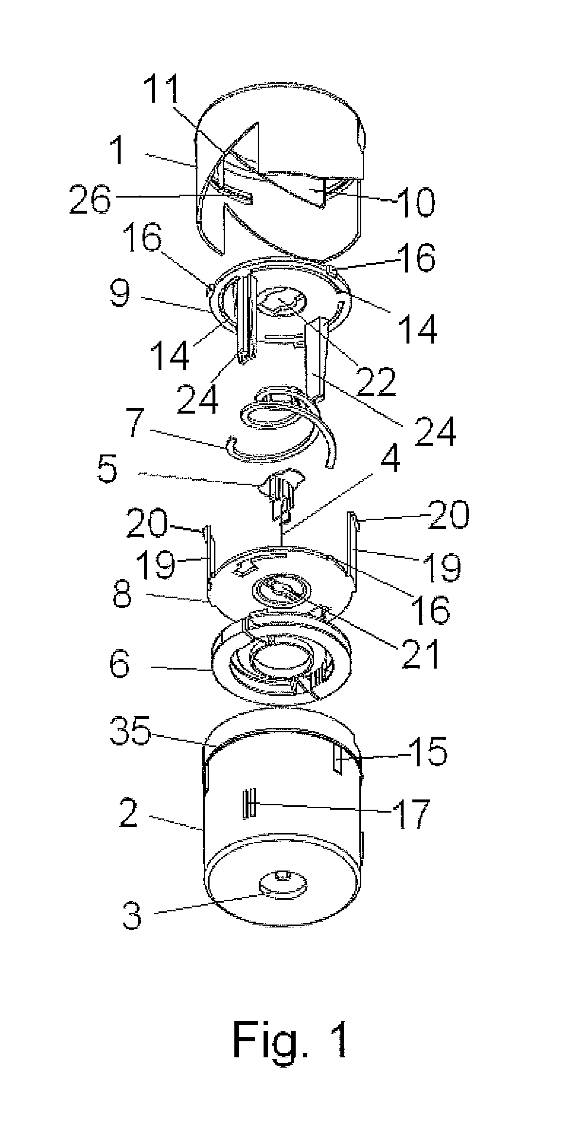
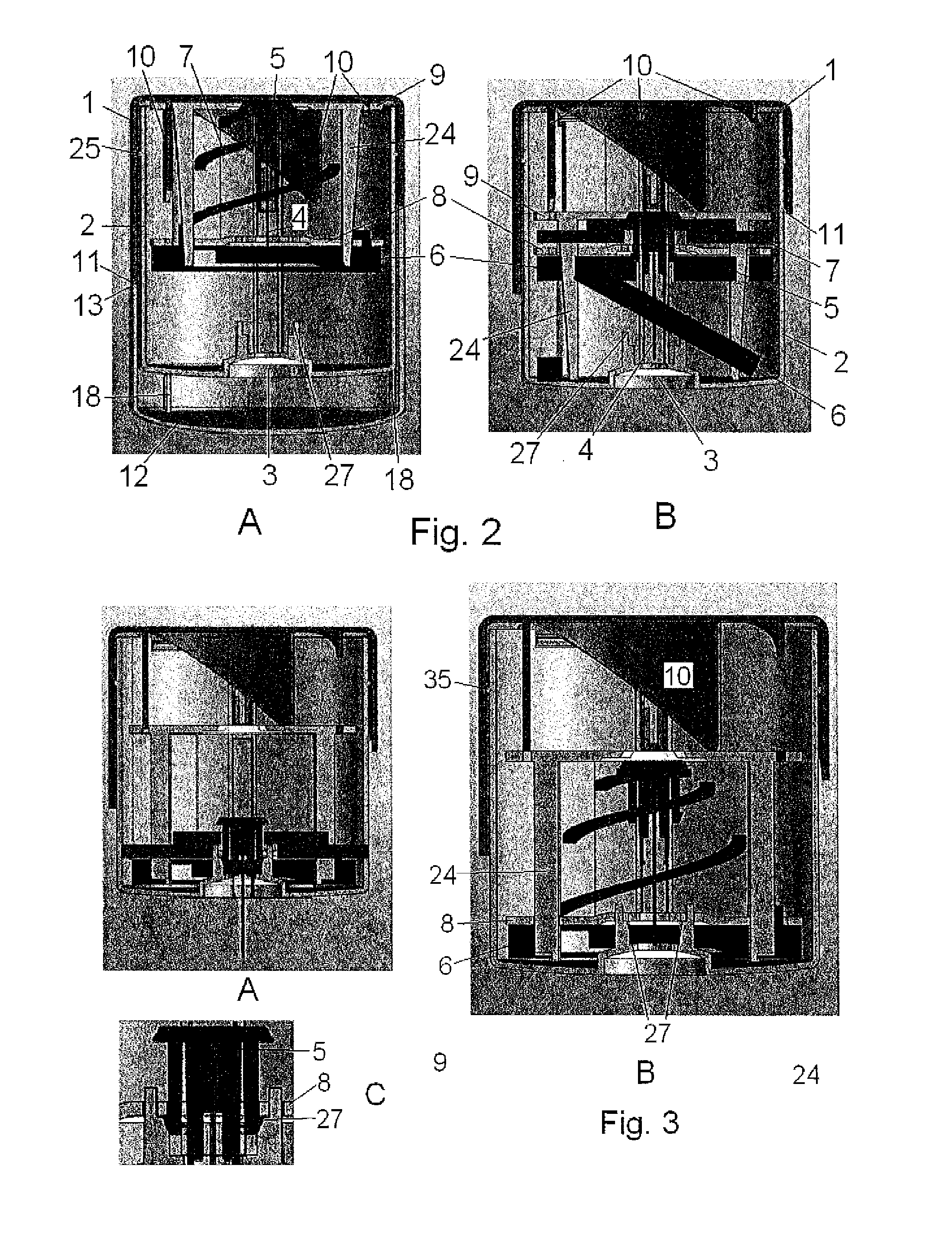
[0078]FIG. 1 shows an inserter device. The embodiment has automatic insertion and automatic retraction of the insertion needle and comprises a housing 1, a cover 2, an insertion needle 4 attached to a needle hub 5, a primary spring 6 used for subcutaneous insertion of the insertion needle 4, a secondary spring 7 used for retraction of the insertion needle 4, a trigger plate 8 and a spring loader 9 i.e. this embodiment comprises 7 separate pieces, 8 including a lid 12 (see FIGS. 2A and 11), and all of the pieces are normally made of moulded plastic except e.g. the insertion needle 4 which might be made of metal.

[0079]The housing 1 is provided with one or more internal wings 10 having a rounded profile and an inclined surface facing the direction of rotation of the housing 1. That the profile is rounded means that the length of the internal wing 10 follows the direction of rotation when the housing 1 is rotated around the longitudinal central axis of the housing 1. The first embodimen...

second embodiment

[0109]FIG. 7 shows the inserter in an unloaded state obtained after insertion of the insertion needle. The primary spring 6 is in a completely unloaded state and the secondary spring 7 is in an almost unloaded state, the secondary spring 7 is providing a force big enough to keep the cover 2 and the housing 1 away from each other in such a degree that the assembled two parts i.e. housing 1 and cover 2, will be as long as possible, and the length is determined by the elevations 32 of the housing 1 getting in contact with the circular protrusion 35 of the cover 2.

[0110]FIGS. 8 and 9 illustrate a third embodiment of an inserter according to the present invention. Parts similar to parts of the first and second embodiments are illustrated with the same reference numbers as used when describing the two former embodiments e.g. the needle hub 5, the primary spring 6, and the release means 27 for the needle hub 5 are similar to the corresponding parts of the first embodiment. The third embodi...

third embodiment

[0112]FIG. 8A shows the inserter device in a ship state which is an unloaded state. As illustrated in FIG. 9, the primary spring 6 which according to this embodiment can be constituted by a single circular rubber band is attached to the top of the cover 2 and supports under the needle hub 5 i.e. the primary spring 6 pulls the needle hub 5 and the top of cover 2 together. The needle hub 5 of this embodiment is constructed with a circular top plate 38 having a diameter small enough to allow the needle hub 5 to slide up and down inside the cylindrical cover 2. The circular top plate 38 has openings 39 allowing for the rubber band constituting the primary spring 6 to pass from the lower side of the needle hub 5 to the top of the cover 2 without by its presence disturbing the sliding movement of the needle hub 5 relative to the cover 2. According to the shown embodiment the rubber band 6 is attached to the top of the cover 2 by winding it around a protruding part of the edge 42, this is ...


PUM


Abstract

The present application relates to an inserter device for inserting a medical device subcutaneous Iy which inserter device comprises a housing (1); a cover (2) which is slidably connected to the housing (1); a hub (5) for an insertion needle (4) which can be moved linearly relative to the housing (1) and relative to the cover (2); a primary spring (6) which moves the hub (5) for the insertion needle (4) relative to the cover (2) and which primary spring (6) is configured to pull the hub (5) for the insertion needle (4) either to a forward or to a retracted position wherein the inserter device further comprises means for biasing the primary spring (6) before insertion.

Description

TECHNICAL FIELD OF THE INVENTION[0001]The invention concerns an insertion device for inserting a medical device or a part of medical device into the subcutaneous or intramuscular area of a patient.BACKGROUND OF THE INVENTION[0002]An inserter device also called inserter or injector is commonly used in the medical field for inserting medical devices, such as infusion sets, sensors or the like, through the skin of a patient in a more or less automated fashion.[0003]Commonly, when using an inserter, the user, i.e. the patient or the treatment provider e.g. nurse, doctor, relative, or the like has to apply a force towards the surface of the skin of the patient in order to provide injection of the medical device or a part of the medical device having the form of a needle, a cannula, a sensor, or the like. This can cause physiological or psychological distress and / or discomfort, and may lead to inappropriate application of the medical device. Many people are afraid of sharp objects, such a...

Claims


Application Information

Patent Timeline
Patent Type & Authority Applications(United States)
IPC IPC(8): A61B17/34
CPCA61M5/158A61M2205/58A61M2005/1585A61M2005/1581A61M39/02
Inventor GYRN, STEFFENTHORUP, SORENDIRAC, HOLGERVIKKELSO, THOMAS HEINSTRUP
Owner UNOMEDICAL AS
Learn More