
Locking device for a drilling device

a technology of latching device and drilling device, which is applied in the direction of drilling machine and method, drilling accessories, core removal, etc., can solve the problems of complicated latches, dangerous, and high maintenance costs of link latches, so as to improve the safety and reliability of drilling operations of drillers, and the effect of less cos

Active Publication Date: 2012-04-19
LES ENTREPRISES PARLEC
View PDF7 Cites 10 Cited by
  • Summary
  • Abstract
  • Description
  • Claims
  • Application Information

AI Technical Summary

Benefits of technology

[0017]The latching device allows drilling operations in the latched position and the retrieval of a sample core in the unlatched position, which is a great advantage.
[0018]In addition, the drilling device improves the driller's safety and the reliability of the drilling operations, which is a great advantage.
[0019]Moreover, the latching device can be manufactured in a less expensive way, which is a great advantage.
[0020]According to one aspect of the invention, the latching device can be used in boreholes oriented downwards or upwards, which is a great advantage.

Problems solved by technology

Spring latches are devices which are satisfactory for drillings from the surface, but they can prove to be dangerous underground because the springs do not always have the necessary strength to maintain the pin in place.
This undesirable phenomenon can for example happen in the presence of a backflow in the hole.
This can cause serious injuries when, at the bottom of the mine, the driller drills upwards while standing in front of the borehole because nothing prevents the mass of the core barrel from crashing upon the driller at full speed.
Link latches form a complicated device that requires a lot of maintenance because of the frequent breakage of the small spring which, when in operation, only abuts small uneven surfaces.
Moreover, this device requires a great travel distance for the retraction of the latches, making it difficult to unlatch once underground.

Method used


Image

  • Locking device for a drilling device
  • Locking device for a drilling device

Examples


Embodiment Construction

[0056]The invention relates to ground drilling tools, and more particularly concerns a latching device with latches for core barrels.

[0057]As detailed hereinbelow, the latching device allows not only to latch a tool at the bottom of a borehole during drilling operations, but also to help hoisting up rock samples, also known as cores.

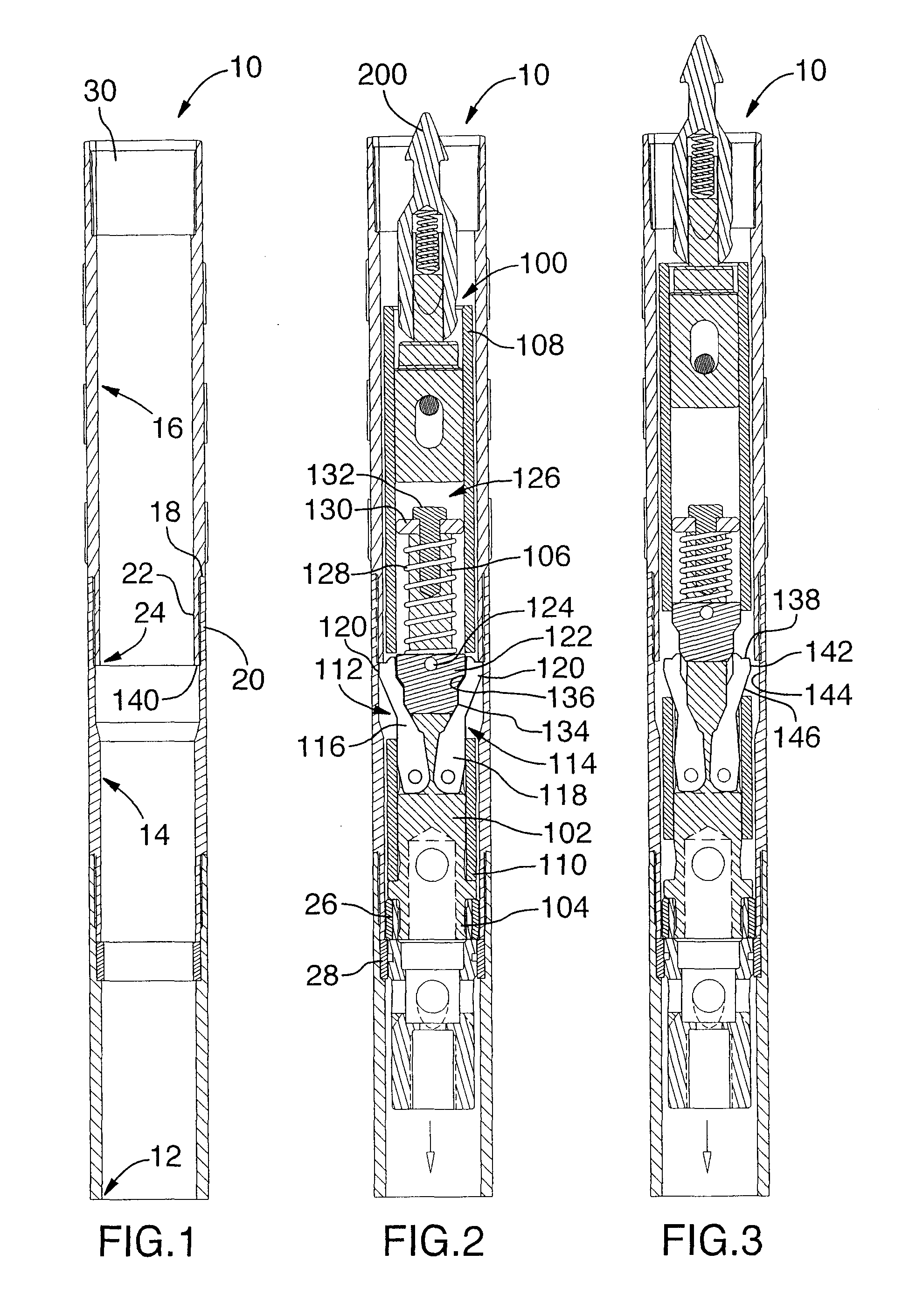
[0058]FIG. 1 shows an outer tube 10 of a drilling device (not shown) used during the drilling of a borehole (not shown), such as a mining borehole or an oil well. In the illustrated embodiment, the outer tube 10 comprises a tubular element 12 designed to be buried in the borehole and through which the drilling will be performed, an adaptor sleeve 14 mounted on the tubular element 12 and a locking sleeve 16 mounted on the adaptor sleeve 14. In a preferred embodiment, the adaptor sleeve 14 is screwed onto the tubular element 12 and the locking sleeve 16 is screwed onto the adaptor sleeve 14. The person skilled in the art of the invention will appreciate th...


PUM


Abstract

Latching device for a drilling device comprising a latching body mountable in an outer tube, an unlatching tube slidably mountable around the latching body, two latches attached to the latching body and pivotable between a deployed position in which the latch cooperates with the outer tube in order to latch the latching body to said outer tube and a retracted position for unlatching the latching body from the outer tube, a piston sliding around the latching body and secured to the unlatching tube, and a compression spring mechanism pressing the piston towards the latches in order to maintain the latches in their deployed position, a pulling force exerted on the unlatching tube compressing the spring mechanism to prevent the piston from pressing against the latches which position themselves in their retracted position.

Description

CROSS-REFERENCE TO RELATED APPLICATIONS[0001]The present patent application claims priority of Canadian patent application No. 2,673,317 filed on Apr. 9, 2009 and entitled LATCHING DEVICE FOR A DRILLING DEVICE, the specification of which is incorporated by reference.FIELD OF THE INVENTION[0002]The present invention generally concerns a latching method and a latching device for a drilling device, and more particularly a latching device for latching a core barrel onto an outer tube buried in a borehole.PRIOR ART[0003]In a typical drilling operation, the driller starts by introducing a tube in the ground. The drilling itself will then be performed inside the tube.[0004]Wire line core barrels are double tube core barrels in which the inner tube, which receives the core, can be hoisted to the surface through the drill string, with the help of an overshot connected to a cable, while the outer tube of the core barrel remains into the drilled hole.[0005]In order to obtain samples at the bot...

Claims


Application Information

Patent Timeline
IPC IPC(8): E21B23/01E21B49/02E21B7/00
CPCE21B25/02E21B23/02
Inventor LAPLANTE, RAYMOND
Owner LES ENTREPRISES PARLEC
Learn More