
System and method for controlled hydroelectric power generation

Inactive Publication Date: 2012-04-12
CLA VAL
View PDF7 Cites 16 Cited by
  • Summary
  • Abstract
  • Description
  • Claims
  • Application Information

AI Technical Summary

Benefits of technology

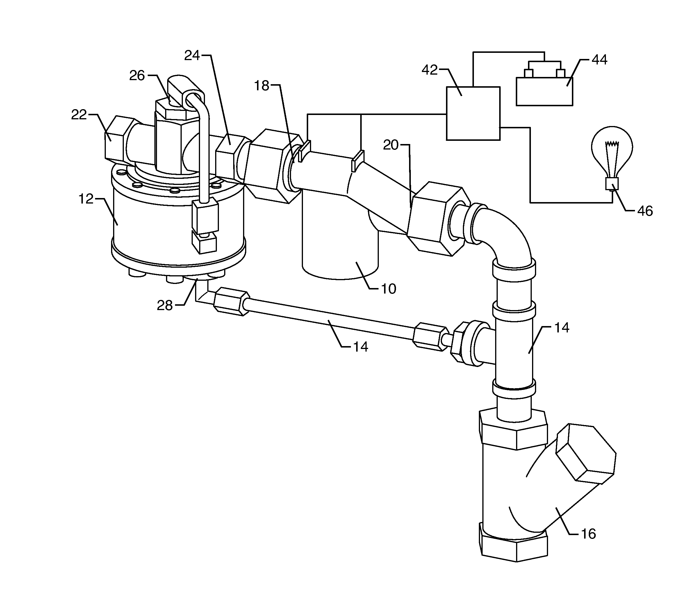
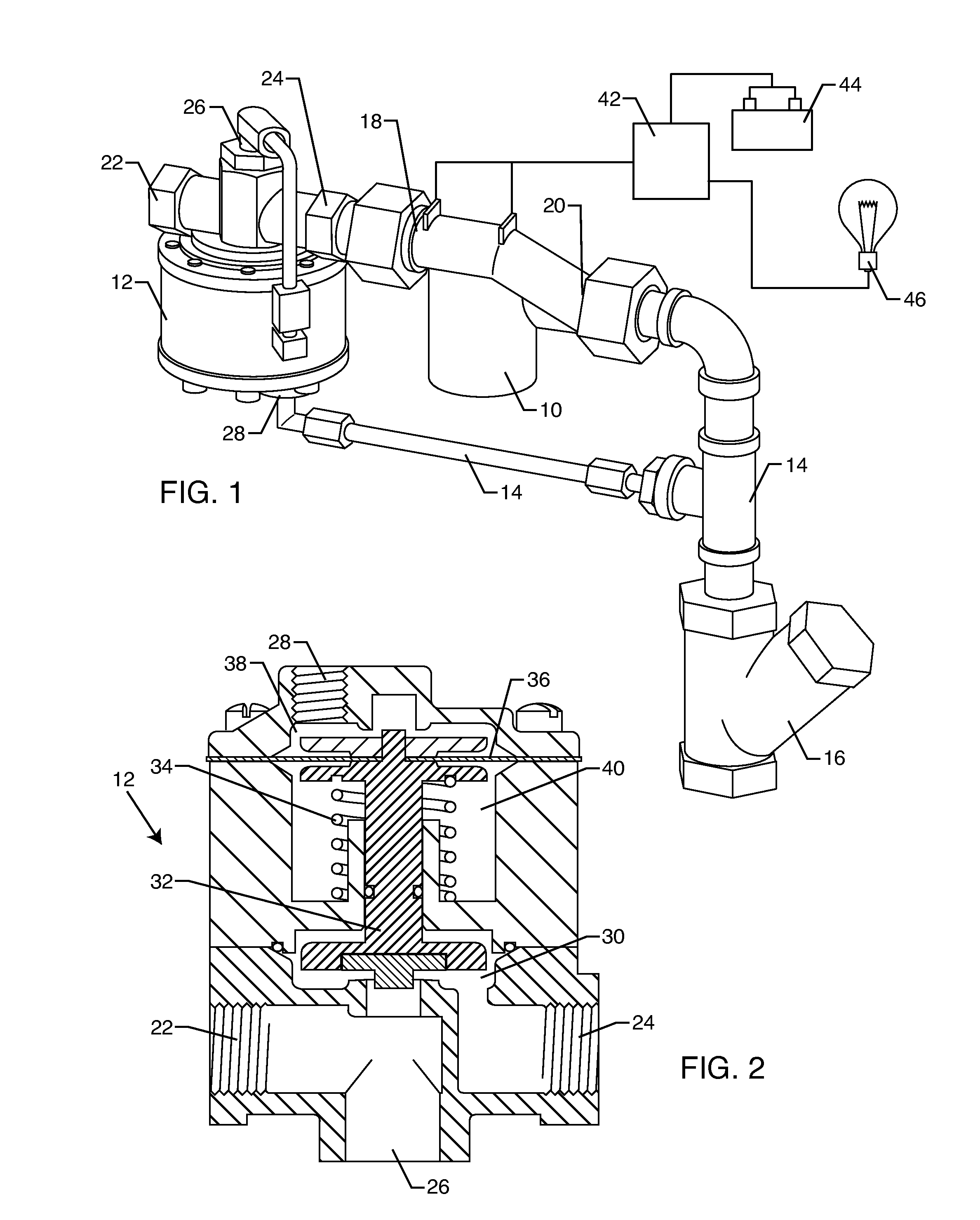
[0013]A differential pressure control pilot limits the differential pressure across the inlet and the outlet of the hydroelectric generator. The differential pressure control pilot comprises a spring-biased hydroelectric diaphragm assembly for maintaining a differential pressure across the hydroelectric generator. The differential pressure control pilot may be disposed upstream or downstream the hydroelectric generator so as to be in fluid communication therewith. In one embodiment, the differential pressure control pilot and the hydroelectric generator are formed as a single component.
[0014]A solenoid may be coupled to the differential co

Problems solved by technology

However, in other cases electricity is not as readily available.
However, such solar panels have drawbacks in that they are limited in their ability to generate power, such as during cloudy days or prolonged adverse weather conditions.
Not only can placement be complicated, but there are concerns as to the solar panel being damaged, such as by vandalism or other means.
However, batteries have a limited amount of electricity which can be provided to these components, and thus have a limited useful life.
Moreover, in some instances, battery power alone is insufficient to provide the necessary electricity for all of the electrical components.
One disadvantage is that the system is constantly running and producing electricity provided that there is a fluid flow through the pipeline, and thus the hydroelectric generator.
Another disadvantage is that the hydroelectric generators themselves wear out prematurely due to their constant motion and action.
However, this system also has disadvantages in that it utilizes a flow-control circuit to sense the discharge flow from the valve outlet and in response regulate the flow of fluid that the valve outlet discharges.
However, the system encounters many of the same disadvantages as the '860 patent system in that excess electricity can be generated, and the turbine which is constantly in operation will wear out prematurely.

Method used


Image

  • System and method for controlled hydroelectric power generation
  • System and method for controlled hydroelectric power generation
  • System and method for controlled hydroelectric power generation

Examples


Embodiment Construction

[0031]The present invention is directed to a system and method for generating electricity in a controlled fluid system, such as a public water distribution network and the like. The system and method of the present invention are particularly useful in applications where a power source is desired but may not be practical. An example would be a need for power in a remote location where a means of supplying power from a power grid may not be possible or convenient. The present invention is intended as a means of generating power where the power can be used to control electronic components associated with a valve, as a power source for lighting in and around the area of the valve such as an underground vault or chamber, etc.

[0032]As will be more fully described herein, the present invention is directed to a system and method which generates electricity in a controlled manner utilizing a differential pressure control device in conjunction with a hydroelectric power generator. The present...


PUM


Abstract

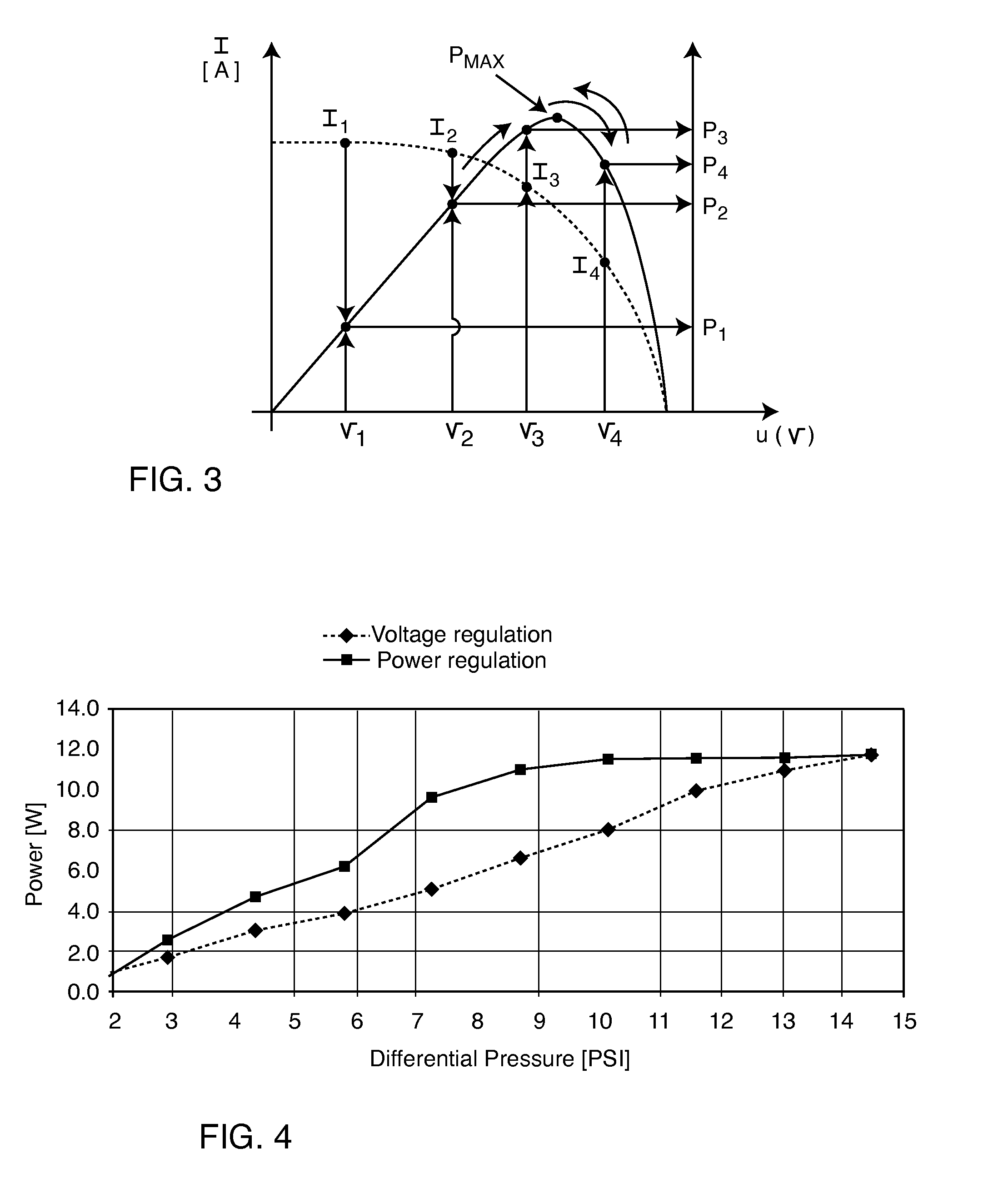
A system for generating electricity in a water distribution network includes a hydroelectric generator in fluid communication with a pipeline or a valve of the network. A differential pressure control pilot limits differential pressure across the hydroelectric generator. A solenoid coupled to the differential control pilot controls water passage through the differential control pilot, and thus the operation of the hydroelectric generator. An electronic controller may be used to optimize power generated by the hydroelectric generator.

Description

BACKGROUND OF THE INVENTION[0001]The present invention is generally directed to hydroelectric generators. More particularly, the present invention is directed to a system and method for generating electricity in a water distribution network in a controlled and optimized manner.[0002]Fluid distribution networks are used in a variety of applications to distribute fluid, such as water, from a central reservoir to one or more remote locations where the fluid is available for use. A fluid distribution network is designed to provide the maximum amount of fluid at a pressure significantly higher than the highest design pressure of all the remote locations. Consequently, fluid-distribution networks typically include pressure-reducing valves to reduce the pressure and flow rate of the fluid before the fluid reaches the remote locations. For example, a typical water-distribution system used by a city to supply water for commercial and residential use includes one or more main water lines that...

Claims


Application Information

Patent Timeline
IPC IPC(8): H02P9/04
CPCF03B13/00F05B2220/20Y02B10/50F05B2220/604F05B2270/3015F05B2220/602
Inventor RE, DANIEL
Owner CLA VAL
Learn More