
Fuel cell vehicle

a fuel cell and vehicle technology, applied in the field of fuel cell vehicles, can solve the problems of brittle part breakage, second tank interference with each other, etc., and achieve the effects of increasing the space in the passenger room, absorbing the impact of collisions, and increasing the fuel cell vehicle's tank capacity

Active Publication Date: 2012-04-05
TOYOTA JIDOSHA KK
View PDF1 Cites 20 Cited by
  • Summary
  • Abstract
  • Description
  • Claims
  • Application Information

AI Technical Summary

Benefits of technology

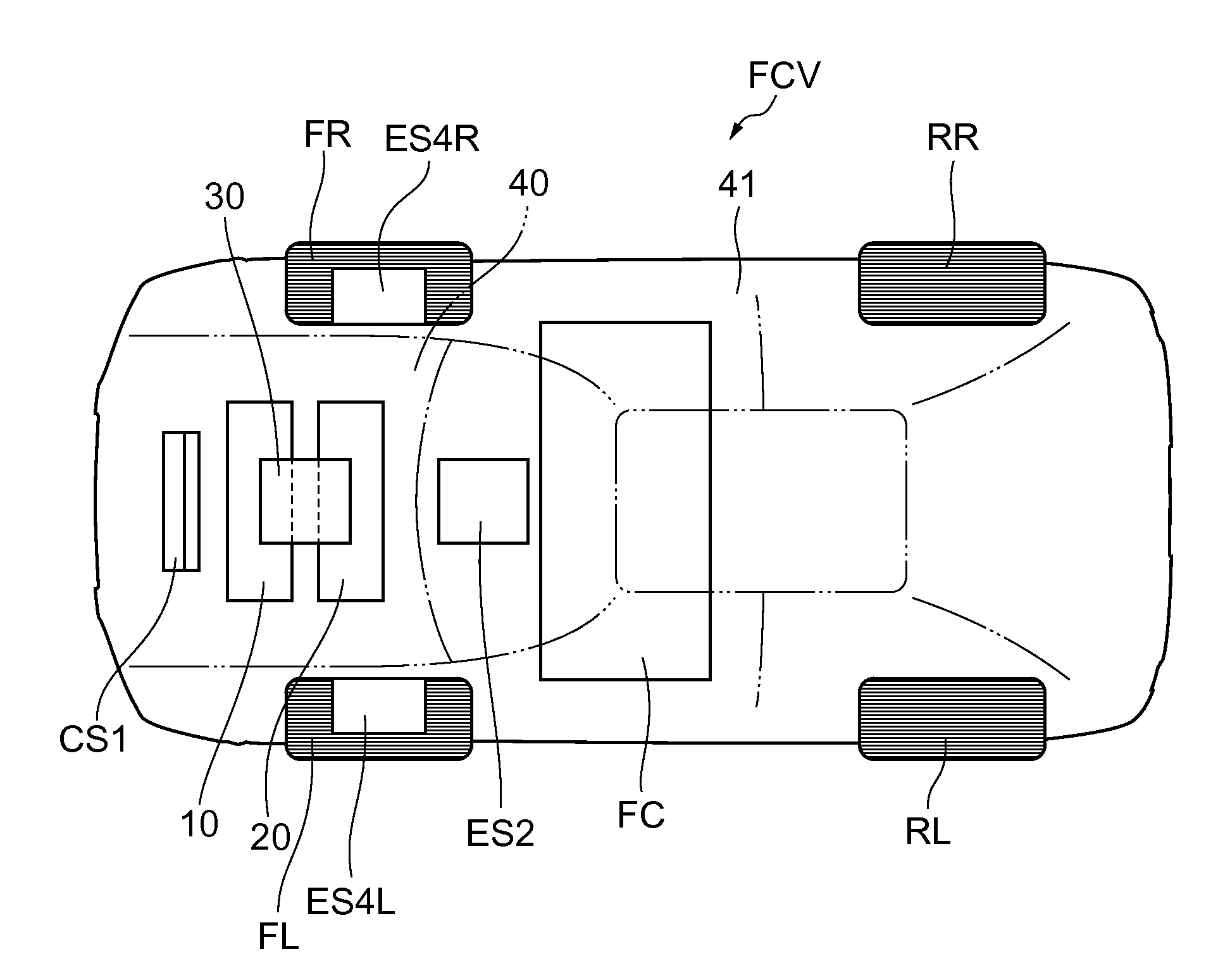
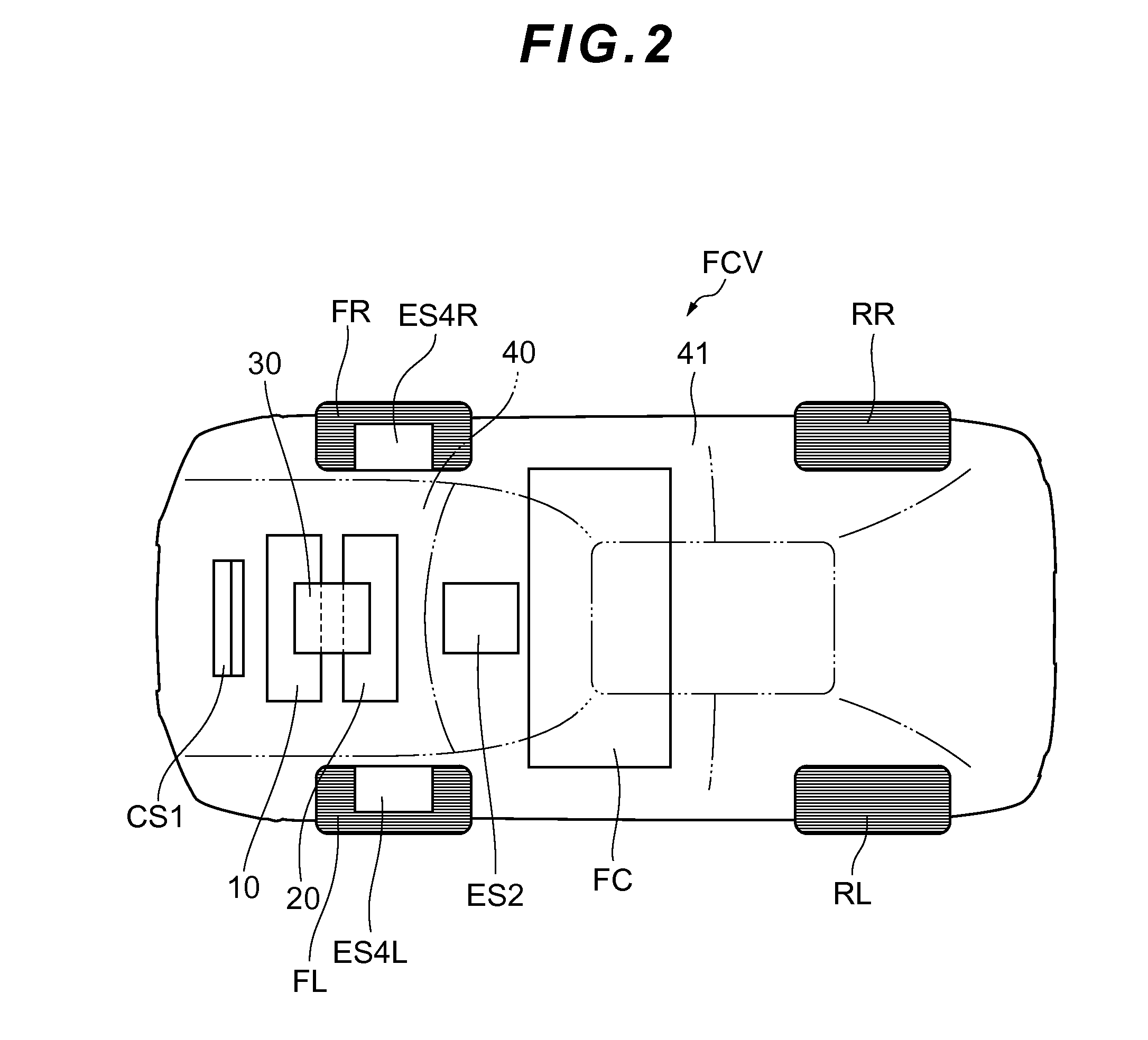
[0008]In the present invention, the first tank and the second tank, which constitute the gas storage section, are arranged in the front area of the fuel cell vehicle, whereby it becomes unnecessary to arrange the first tank and the second tank below the passenger room, making it possible to contribute to an increase in the space in the passenger room. Besides, because weight distribution can be performed in such a manner as to position heavy loads near the front area, it is possible to keep driving performance good when the front wheels are used as driving wheels. Furthermore, in the present invention, attention is paid to the characteristics of the first and second tanks constituting the gas storage section. The inside of the first and second tanks which store a reaction gas or a raw material gas obtains a high pressure, and hence the tanks are fabricated robust in such a manner as to be able to withstand the high pressure and in order to prevent breakage by the impact from the outside. In the present invention, by using the strength of the first tank and the second tank, it is ensured that even when mutual interference occurs, this mutual interference does not lead to breakage. Specifically, tanks constituting the gas storage section are divided into at least two parts, a first tank and a second tank, and the tanks are arranged so that the positions of the tanks are out of alignment in a vertical direction. Because the first tank and the second tank are arranged in an off-set manner like this, even when the fuel cell vehicle collides and an impact is applied, with the result that the first tank and the second tank come close to each other and interfere with each other, it is possible to absorb the impact while changing the relative positional relation by increasing the amount of offset in a vertical position.
[0009]In the fuel cell vehicle of the present invention, it is also preferred that the second tank be arranged in a position lower than the first tank. When an impact by a collision as described above is applied, the forward first tank moves backward and the backward second tank moves forward, resulting in a condition in which the first tank and the second tank interfere with each other. Because in this preferable aspect the second tank is arranged in a position lower than the first tank, it is possible to adopt a configuration which is such that in the case where the tanks come close to each other and interfere with each other, the backward second tank moves backward while being pushed further below by the first tank. And it becomes possible to adopt a configuration which is such that the impetus of the backward movement of the forward first tank is greatly reduced by the interference with the second tank. Therefore, it becomes possible to control the direction in which the first tank and the second tank move backward during a collision and hence it is possible to positively avoid a situation in which the first tank and the second tank hit passengers and other equipment.
[0010]In the fuel cell vehicle of the present invention, it is also preferred that the first tank and the second tank be fixed to a cross member extending in the width direction of the fuel cell vehicle, and that the cross member have a brittle portion between a part which fixes the above-described first tank and a part which fixes the above-described second tank. When an impact by a collision as described above is applied, the forward first tank moves backward and the backward second tank moves forward, and hence external forces are applied to the cross member which fixes the first tank and the second tank, with the result that breakage occurs from the brittle portion. For this reason, by adjusting the shape of the cross member and the position and the mode of the brittle portion, it becomes easy to control the behavior of the first tank and the second tank during a collision. Furthermore, it becomes possible to regulate the behavior of the first tank and the second tank after a collision by using the cross member and, therefore, it is possible to reduce the amount of movement of the first tank and the second tank after a collision.
[0013]According to the present invention, it is possible to provide a fuel cell vehicle which enables compatibility to be ensured between an increase in the tank capacity of the fuel cell vehicle and an increase in the space in a passenger room and a trunk, and is capable of absorbing the impact of a collision even if the collision occurs.

Problems solved by technology

When an impact by a collision as described above is applied, the forward first tank moves backward and the backward second tank moves forward, resulting in a condition in which the first tank and the second tank interfere with each other.
When an impact by a collision as described above is applied, the forward first tank moves backward and the backward second tank moves forward, and hence external forces are applied to the cross member which fixes the first tank and the second tank, with the result that breakage occurs from the brittle portion.

Method used


Image

  • Fuel cell vehicle
  • Fuel cell vehicle
  • Fuel cell vehicle

Examples


Embodiment Construction

[0022]Hereinafter an embodiment of the present invention will be described with reference to the accompanying drawings. In order to facilitate the understanding of the description, in each of the drawings the same component elements bear the same reference symbols as far as possible and repetition of descriptions thereof are omitted.

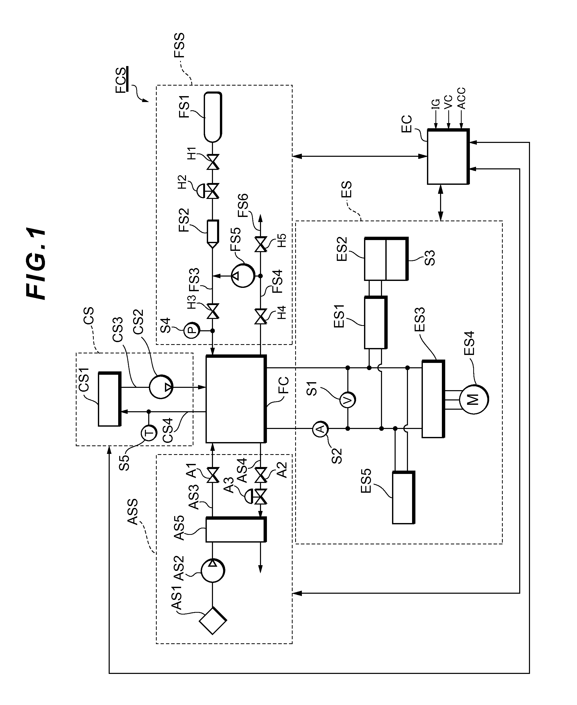
[0023]First, with reference to FIG. 1 a description will be given of a fuel cell system FCS to be mounted on a fuel cell vehicle which is an embodiment of the present invention. FIG. 1 is a diagram showing the system configuration of a fuel cell system FCS which functions as a vehicle-mounted power supply system of a fuel cell vehicle. The fuel cell system FCS can be mounted on a vehicle, such as a fuel cell vehicle (FCV), an electric vehicle, and a hybrid vehicle.

[0024]The fuel cell system FCS is provided with a fuel cell FC, an oxidation gas supply system ASS, a fuel gas supply system FSS, a power system ES, a cooling system CS, and a controller EC. Th...


PUM


Abstract

This fuel cell vehicle FCV is provided with a fuel cell FC as well as a first tank and a second tank, which store a reaction gas to be supplied to the fuel cell FC. The first tank and the second tank are arranged in the front area of the fuel cell vehicle FCV. The second tank is arranged nearer to a rear area than the first tank and arrangement is performed so that the positions of the tanks are out of alignment in a vertical direction. This configuration enables compatibility to be ensured between an increase in the tank capacity of the fuel cell vehicle and an increase in the space in a passenger room and a trunk, and is capable of absorbing the impact of a collision even if the collision occurs.

Description

BACKGROUND OF THE INVENTION[0001]1. Field of the Invention[0002]The present invention relates to a fuel cell vehicle on which a fuel cell is mounted.[0003]2. Description of the Related Art[0004]As such a fuel cell vehicle, there is known a fuel cell vehicle in which a fuel cell and a tank storing a reaction gas are arranged under the floor of a cabin. However, in a fuel cell vehicle in which a tank is arranged under the floor as in this case, an increase in the capacity of the tank results in a reduction in the space of a passenger room. Therefore, it has been difficult to ensure the compatibility between an increase in the tank capacity and an increase in the space in the passenger room. To cope with this situation, in order to ensure the compatibility between an increase in the tank capacity and an increase in the space in the passenger room, it has been proposed to arrange the tank in the vicinity of an axle in the front area of the fuel cell vehicle (refer to Japanese Patent Lai...

Claims


Application Information

Patent Timeline
Patent Type & Authority Applications(United States)
IPC IPC(8): B60R16/04
CPCB60K1/04B60L2240/12B60K15/07B60K2001/0438B60K2015/03315B60K2015/0637B60K2015/0675B60Y2306/01H01M8/04201H01M16/006H01M2250/20Y02E60/50Y02T90/32B60L11/1898B60Y2400/61Y02T90/34B60L11/1881B60L11/1892B60K7/0007B60L50/72B60L58/30B60L58/33Y02E60/10Y02T90/40
Inventor OHASHI, YASUHIKO
Owner TOYOTA JIDOSHA KK
Learn More